XLS Series Power Amplifi ers
Front Panel Features
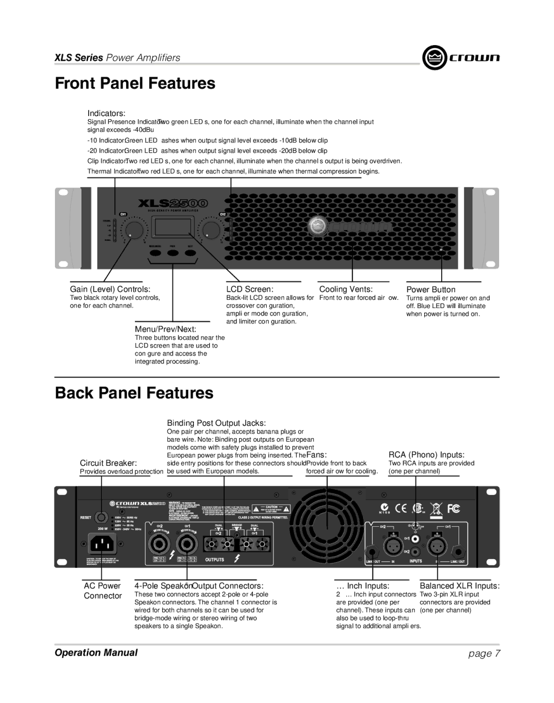
Indicators:
Signal Presence Indicator: Two green LED’s, one for each channel, illuminate when the channel input signal exceeds
Clip Indicator: Two red LED’s, one for each channel, illuminate when the channel’s output is being overdriven.
Thermal Indicator: Two red LED’s, one for each channel, illuminate when thermal compression begins.
Gain (Level) Controls:
Two black rotary level controls, one for each channel.
LCD Screen: | Cooling Vents: | Power Button |
Front to rear forced air flow. | Turns amplifier power on and | |
crossover configuration, |
| off. Blue LED will illuminate |
amplifier mode configuration, |
| when power is turned on. |
and limiter configuration. |
|
|
Menu/Prev/Next:
Three buttons located near the LCD screen that are used to configure and access the integrated processing.
Back Panel Features
Binding Post Output Jacks:
|
|
|
|
|
|
| One pair per channel, accepts banana plugs or |
|
|
|
|
|
|
|
|
|
|
|
|
|
|
|
|
| ||||
|
|
|
|
|
|
| bare wire. Note: Binding post outputs on European |
|
|
|
|
|
|
|
|
|
|
|
|
|
|
|
|
| ||||
|
|
|
|
|
|
| models come with safety plugs installed to prevent |
| Fans: | RCA (Phono) Inputs: |
|
| ||||||||||||||||
Circuit Breaker: | European power plugs from being inserted. The |
|
|
| ||||||||||||||||||||||||
side entry positions for these connectors should |
| Provide front to back | Two RCA inputs are provided |
|
| |||||||||||||||||||||||
Provides overload protection | be used with European models. |
| forced airflow for cooling. | (one per channel) |
|
| ||||||||||||||||||||||
|
|
|
|
|
|
|
|
|
|
|
|
|
|
|
|
|
|
|
|
|
|
|
|
|
|
|
|
|
|
|
|
|
|
|
|
|
|
|
|
|
|
|
|
|
|
|
|
|
|
|
|
|
|
|
|
|
|
|
|
|
|
|
|
|
|
|
|
|
|
|
|
|
|
|
|
|
|
|
|
|
|
|
|
|
|
|
|
|
|
|
|
|
|
|
|
|
|
|
|
|
|
|
|
|
|
|
|
|
|
|
|
|
|
|
|
|
|
|
|
|
|
|
|
|
|
|
|
|
|
|
|
|
|
|
|
|
|
|
|
|
|
|
|
|
|
|
|
|
|
|
|
|
|
|
|
|
|
|
|
|
|
|
|
|
|
|
|
|
|
|
|
|
|
|
|
|
|
|
|
|
|
|
|
|
|
|
|
|
|
|
|
|
|
|
|
|
|
|
|
|
|
|
|
|
|
|
|
|
|
|
|
|
|
|
|
|
|
|
|
|
|
|
|
|
|
|
|
|
|
|
|
|
|
|
|
|
|
|
|
|
|
|
|
|
|
|
|
|
|
|
|
|
|
|
|
|
|
|
|
|
|
|
|
|
|
|
|
|
|
|
|
|
|
|
|
|
|
|
|
|
|
|
|
|
|
|
|
|
|
|
|
|
|
|
|
|
|
|
|
|
|
|
|
|
|
|
|
|
|
|
|
|
|
|
|
|
|
|
|
|
|
|
|
|
|
|
|
|
|
|
|
|
|
|
|
|
|
|
|
|
|
|
|
|
|
|
|
|
|
|
|
|
|
|
|
|
|
|
|
|
|
|
|
|
|
|
|
|
|
|
|
|
|
|
|
|
AC Power Connector
4-Pole Speakon® Output Connectors:
These two connectors accept
¼ Inch Inputs:
2 – ¼ Inch input connectors are provided (one per channel). These inputs can also be used to
Balanced XLR Inputs:
Two
Operation Manual | page 7 |
