Theory
| to the cutoff level under static (no signal) conditions. |
High Side (HS) | This is because PNP devices require greater drive |
The High Side (HS) of the bridge operates much like | current. |
a conventional bipolar |
|
As the input drive voltage becomes more positive, the | HS bias is regulated by Q18, the Bias Servo. Q18 is a |
HS NPN conducts and delivers positive voltage to the | Vbe multiplier which maintains approximately 3.3V |
load. Eventually the NPN devices reach full conduc- | Vce under static conditions. The positive and negative |
tion and +Vcc is across the load. At this time the HS | halves of the HS output are in parallel with this 3.3V. |
PNP is biased off. When the drive signal is negative | With a full |
going, the HS PNP conducts to deliver | predrivers and drivers, the balance of voltage results |
and the HS NPN stage is off. | in approximately .35V drop across the bias resistors in |
| the positive half, and about .5V across the bias resistor |
The output of the +LVA drives the base of predriver | in the negative half. Q18 conduction (and thus bias) is |
device. Together, the predriver and driver form the | adjustable. |
first two parts of the |
|
biased class AB. They provide output drive through | A diode string prevents excessive charge build up |
the bias resistor, bypassing the output devices, at | within the high conduction output devices when off. |
levels below about 100mW. An RLC network between | Flyback diodes shunt |
the predriver and driver provide phase shift compen- | loads to the power supply to protect output devices |
sation and limit driver base current to safe levels. | from dangerous reverse voltage levels. An output |
Output devices are biased class B, just below cutoff. | terminating circuit blocks RF on output lines from |
At about 100mW output they switch on to conduct high | entering the amplifier through its output connectors. |
current to the load. Together with predriver and driver, |
|
the output device provide an overall class AB+B | Low Side (LS) |
output. | The Low Side (LS) operates quite differently. The |
| power supply bridge rectifier is not ground refer- |
The negative half of the HS is almost identical to the | enced, nor is the secondary of the main transformer. |
positive half, except that the devices are PNP. One | In other words, the high voltage power supply floats |
difference is that the PNP bias resistor is slightly | with respect to ground, but ±Vcc remain constant with |
greater in value so that PNP output devices run closer |
|
+ ![]()
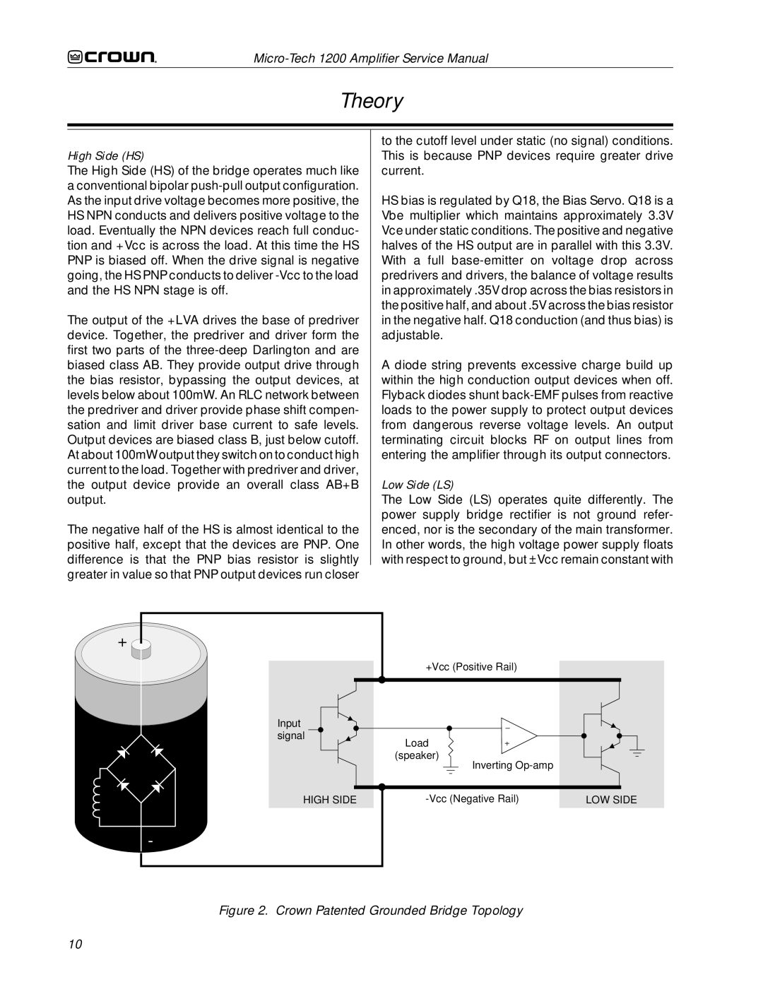
| +Vcc (Positive Rail) |
|
Input |
|
|
signal | Load |
|
|
| |
| (speaker) |
|
| Inverting |
|
HIGH SIDE | LOW SIDE |
-
Figure 2. Crown Patented Grounded Bridge Topology
10