K Series specifications
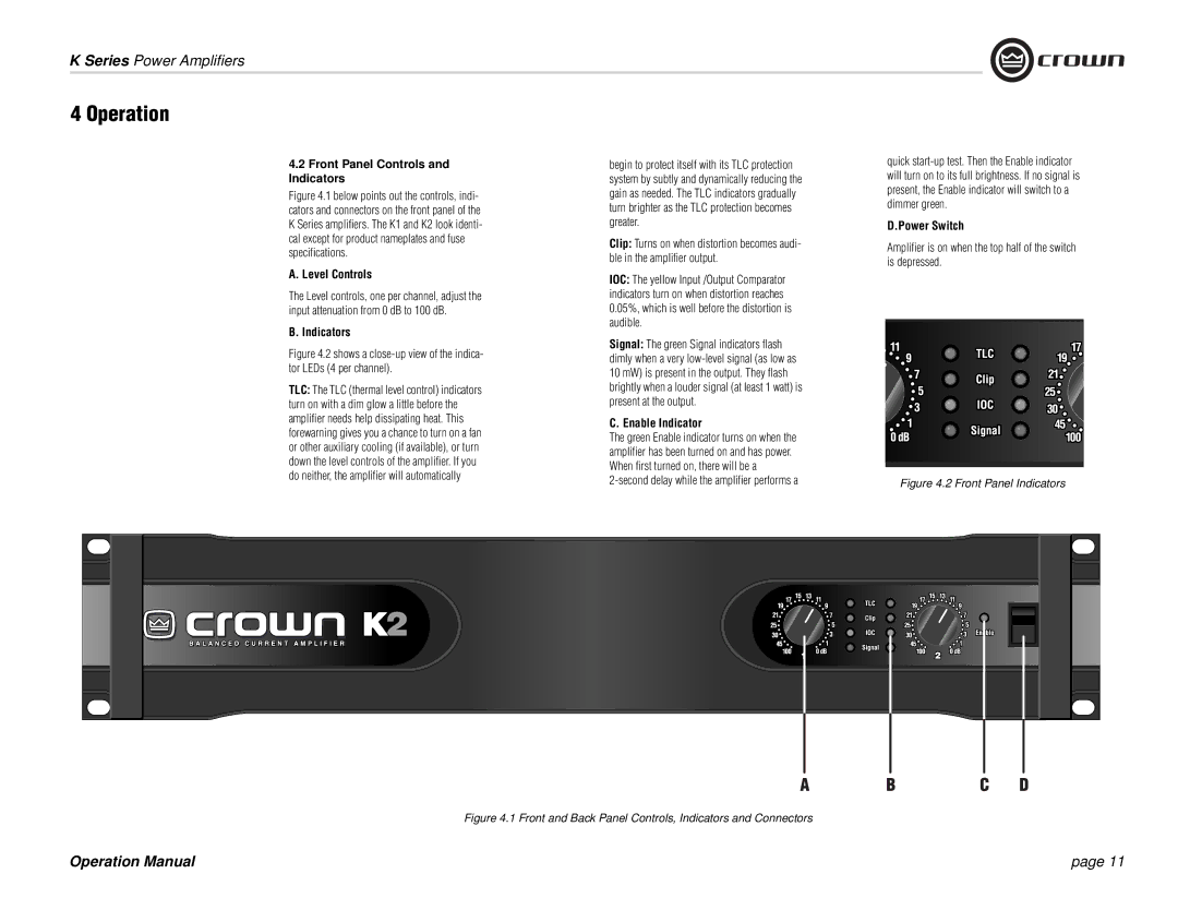
Crown Audio K Series amplifiers represent the pinnacle of professional audio amplification, delivering exceptional power, performance, and reliability. Designed for a wide range of applications, including live sound reinforcement and installation scenarios, the K Series is a testament to the innovation and engineering excellence that Crown Audio is known for.One of the standout features of the K Series is its output power. With models available that provide up to 4,000 watts per channel at 4 ohms, these amplifiers can drive even the most demanding speaker systems with ease. This makes the K Series ideal for large venues and events where high sound pressure levels are required.
The K Series amplifiers incorporate advanced technology such as Crown's highly efficient Class-D design, which not only reduces weight but also minimizes power consumption, making them more environmentally friendly. This efficiency allows for greater power density, meaning more power can be delivered without excessive heat generation. In addition, the K Series uses a patented "Power Factor Correction" technology, ensuring that the amplifiers perform consistently under varying load conditions, which is crucial for maintaining sound quality in professional applications.
Another key characteristic of the K Series is its robust build quality. Constructed with durable materials and featuring an efficient cooling system, these amplifiers are designed to withstand the rigors of touring and installation use. Furthermore, the K Series is equipped with comprehensive protection circuitry, including over-temperature, short circuit, and RF interference protection, guaranteeing reliable operation even in challenging environments.
The K Series also offers advanced connectivity options, with models equipped with digital signal processing capabilities. This allows users to tailor the audio output to suit specific acoustic requirements, including equalization, delays, and limiting. Additionally, the K Series is compatible with the Harman HiQnet Network, enabling remote monitoring and control via a user-friendly graphical interface.
With a combination of high output power, advanced technologies, and robust design, the Crown Audio K Series amplifiers provide exceptional performance for professionals seeking reliable, high-quality sound amplification solutions. Whether for concert tours, festivals, or permanent installations, the K Series continues to set the standard in audio amplification. Its features and innovations ensure that it remains a preferred choice among audio professionals worldwide, delivering powerful, crystal-clear sound that meets the demands of any audio application.

