Fig. 3
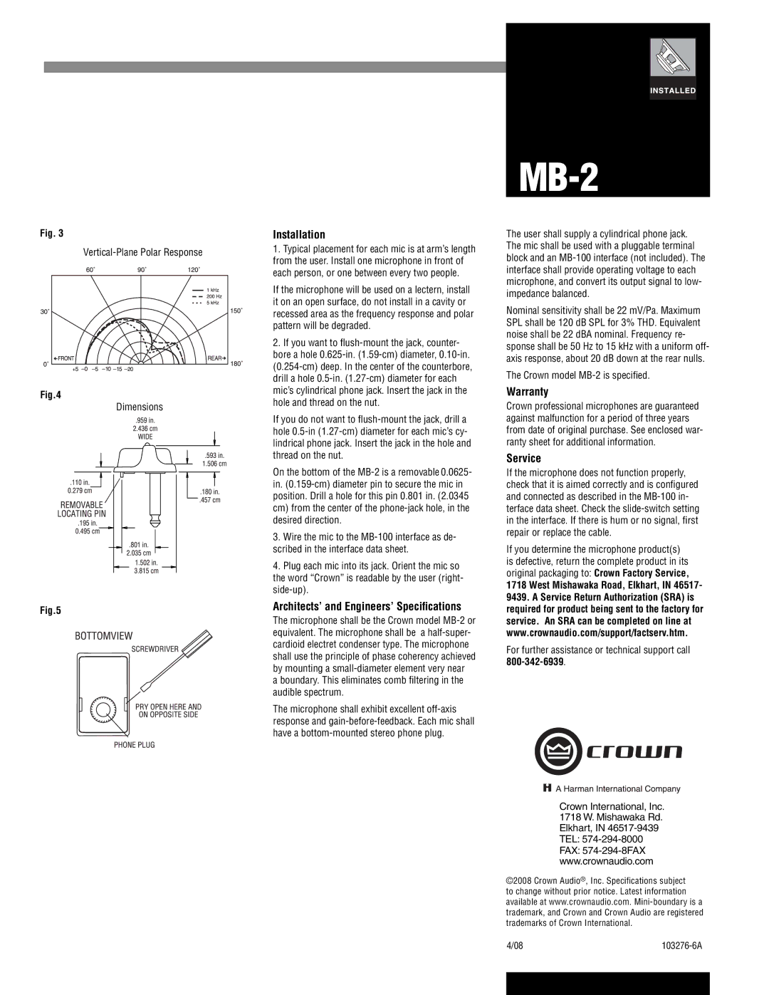
Fig.4
Dimensions
Fig.5
Installation
1.Typical placement for each mic is at arm’s length from the user. Install one microphone in front of each person, or one between every two people.
If the microphone will be used on a lectern, install it on an open surface, do not install in a cavity or recessed area as the frequency response and polar pattern will be degraded.
2.If you want to flush-mount the jack, counter-
bore a hole
If you do not want to
On the bottom of the
3.Wire the mic to the
4.Plug each mic into its jack. Orient the mic so the word “Crown” is readable by the user (right-
Architects’ and Engineers’ Specifications
The microphone shall be the Crown model
a boundary. This eliminates comb filtering in the audible spectrum.
The microphone shall exhibit excellent
MB-2
The user shall supply a cylindrical phone jack. The mic shall be used with a pluggable terminal block and an
Nominal sensitivity shall be 22 mV/Pa. Maximum SPL shall be 120 dB SPL for 3% THD. Equivalent noise shall be 22 dBA nominal. Frequency re- sponse shall be 50 Hz to 15 kHz with a uniform off- axis response, about 20 dB down at the rear nulls.
The Crown model
Warranty
Crown professional microphones are guaranteed against malfunction for a period of three years from date of original purchase. See enclosed war- ranty sheet for additional information.
Service
If the microphone does not function properly, check that it is aimed correctly and is configured and connected as described in the
If you determine the microphone product(s) is defective, return the complete product in its original packaging to: Crown Factory Service, 1718 West Mishawaka Road, Elkhart, IN 46517- 9439. A Service Return Authorization (SRA) is required for product being sent to the factory for service. An SRA can be completed on line at www.crownaudio.com/support/factserv.htm.
For further assistance or technical support call
Crown International, Inc. 1718 W. Mishawaka Rd. Elkhart, IN
©2008 Crown Audio®, Inc. Specifications subject to change without prior notice. Latest information available at www.crownaudio.com.
4/08 |