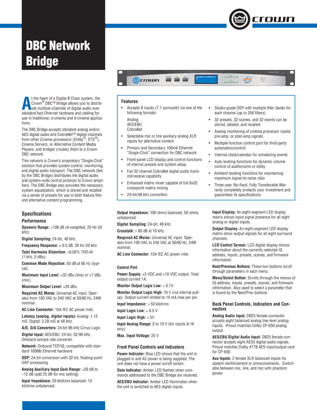
DBC Network Bridge
t the heart of a Digital B Chain system, the ACrown® DBCTM Bridge allows you to distrib-
ute multiple channels of digital audio over standard fast Ethernet hardware and cabling for use in traditional,
The DBC Bridge accepts standard analog and/or AES digital audio and CobraNetTM digital channels from other Cinema processors (Dolby®, DTS®), Cinema Servers, or Alternative Content Media Players; and bridges (routes) them to a Crown DBC network.
This network is Crown’s proprietary
Features
• Accepts 8 inputs (7.1 surround) via one of the | • | |
following formats: | each channel (up to 256 filters) | |
Analog | • 32 presets, 32 scenes, and 32 events can be | |
AES/EBU | stored, labeled, and recalled | |
CobraNet | • Analog monitoring of cinema processor inputs, | |
• Selectable mic or line auxiliary analog XLR | ||
inputs for alternative content | • | |
• Primary and Secondary 100mb Ethernet | ||
automation/control | ||
• Internal clock/calendar for scheduling events | ||
• | ||
• Auto leveling functions for dynamic volume | ||
of internal presets and system setup | ||
control of auditoriums or lobby | ||
• Full | ||
• Ambient leveling functions for maintaining | ||
mit/receive capability | ||
maximum | ||
• Enhanced matrix mixer capable of full 8x32 | ||
• | ||
crosspoint matrix mixing | ||
ranty completely protects your investment and | ||
• | ||
guarantees its specifications |
Specifications
Performance
Dynamic Range: >108 dB
Digital Sampling:
Frequency Response: ± 0.5 dB, 20
Total Harmonic Distortion: <0.05% THD+N (1 kHz, 0 dBu).
Common Mode Rejection: 50 dB at 60 Hz (typi- cal).
Maximum Input Level: +32 dBu (line) or +7 dBu (mic).
Maximum Output Level: +20 dBu.
Required AC Mains: Universal AC input. Oper- ates from 100 VAC to 240 VAC at 50/60 Hz, 24W nominal.
AC Line Connector: 15A IEC AC power inlet.
Latency (analog, digital inputs): Analog: 1.13
mS. Digital: 2.28 mS at 48 kHz.
A/D, D/A Converters:
Digital Input: AES/EBU,
Network: Onboard TCP/IQ, compatible with stan- dard 100Mb Ethernet hardware
DSP:
Analog Auxiliary Input Gain Range: +20 dB to
Input Impedance: 20 kilohms balanced, 10 kilohms unbalanced.
Output Impedance: 100 ohms balanced, 50 ohms unbalanced.
Digital Sampling:
Crosstalk: > 80 dB at 10 kHz.
Required AC Mains: Universal AC input. Oper- ates from 100 VAC to 240 VAC at 50/60 Hz, 24W nominal.
AC Line Connector: 15A IEC AC power inlet.
Control Port
Power Supply: +5 VDC and +10 VDC output. Total output current 1A.
Monitor Output Logic Low: < 0.1V
Monitor Output Logic High: 10 V (via internal pull- up). Output current limited to 10 mA max per pin.
Input Impedance: > 50 kilohms
Input Logic Low: < 0.5 V
Input Logic High: > 5V
Input Analog Range: 0 to 10 V (for inputs
Max. Input Voltage: 25 V
Front Panel Controls and Indicators
Power Indicator: Blue LED shows that the unit is plugged in and AC power is being supplied. The unit does not have a power on/off switch.
Data Indicator: Amber LED flashes when com- mands addressed to the DBC Bridge are received.
AES/EBU Indicator: Amber LED illuminates when the unit is switched to AES digital inputs.
Input Display: An
Output Display: An
LCD Control Screen: LCD digital display shows information about the currently selected IQ address, inputs, presets, scenes, and firmware information.
Next/Previous Buttons: These two buttons scroll through parameters in each menu.
Menu/Select Button: Scrolls through the menus of IQ address, inputs, presets, scenes, and firmware information. Also used to select a parameter that is found by the Next/Prev buttons.
Back Panel Controls, Indicators and Con- nectors
Analog Audio Input: DB25 female connector accepts eight balanced analog
AES/EBU Digital Audio Input: DB25 female con- nector accepts eight AES3 digital audio signals. Pinout matches Dolby #778 AES input/output card for
Aux Inputs: 2 female XLR balanced inputs for speech reinforcement or announcements. Switch- able between mic, line, and mic with phantom power.
