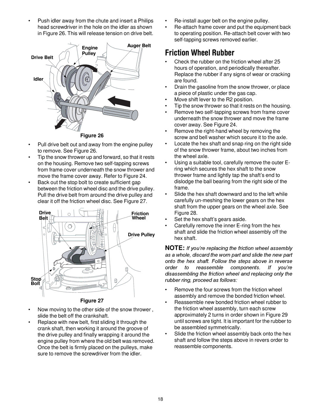
Push idler away from the chute and insert a Philips head screwdriver in the hole on the idler as shown in Figure 26. This will release tension on drive belt.

Engine

Auger Belt


Pulley


Drive Belt

Idler

Figure 26

Pull drive belt out and away from the engine pulley to remove. See Figure 26.

Tip the snow thrower up and forward, so that it rests on the housing. Remove two self-tapping screws from frame cover underneath the snow thrower and move the frame cover away. Refer to Figure 24.

Back out the stop bolt to create sufficient gap between the friction wheel disc and the drive pulley. Pull the drive belt from around the drive pulley and clear it off the friction wheel disc. See Figure 27.

Drive

Friction

Belt

Wheel


Drive Pulley

Stop

Bolt

Figure 27

Now moving to the other side of the snow thrower , slide the belt off the crankshaft.

Replace with new belt, first sliding it through the crank shaft, then working it around the groove of the drive pulley and finally wrapping it around the engine pulley from where the old belt was removed. Once the belt is firmly placed on the pulleys, make sure to remove the screwdriver from the idler.

Re-install auger belt on the engine pulley.

Re-attach frame cover and put the equipment back to operating position. Re-attach belt cover with two self-tapping screws removed earlier.

Friction Wheel Rubber

Check the rubber on the friction wheel after 25 hours of operation, and periodically thereafter. Replace the rubber if any signs of wear or cracking are found.

Drain the gasoline from the snow thrower, or place a piece of plastic under the gas cap.

Move shift lever to the R2 position.

Tip the snow thrower so that it rests on the housing.

Remove two self-tapping screws from frame cover underneath the snow thrower and move the frame cover away. See Figure 24.

Remove the right-hand wheel by removing the screw and bell washer which secure it to the axle.

Locate the hex shaft and snap ring on the right side of the snow thrower frame, about two inches from the wheel axle.

Using a suitable tool, carefully remove the outer E- ring which secures the hex shaft to the snow thrower frame and lightly tap the shaft’s end to dislodge the ball bearing from the right side of the frame.

Slide the hex shaft downward and to the left while carefully un-meshing the lower gears on the hex shaft from the upper gears on the wheel axle. See Figure 28.

Set the hex shaft’s gears aside.

Carefully remove the inner E-ring from the hex shaft and slide the friction wheel assembly off the hex shaft.

NOTE: If you’re replacing the friction wheel assembly as a whole, discard the worn part and slide the new part onto the hex shaft. Follow the steps above in reverse order to reassemble components. If you’re disassembling the friction wheel and replacing only the rubber ring, proceed as follows:

Remove the four screws from the friction wheel assembly and remove the bonded friction wheel.

Reassemble new bonded friction wheel rubber to the friction wheel assembly, turn each screw approximately 2 turns in order shown in Figure 29 until screws are tight. It is important for the rubber to be assembled symmetrically.

Slide the friction wheel assembly back onto the hex shaft and follow the steps above in revers order to reassemble components.

18

Page 18
Image 18
Cub Cadet 600 manual Friction Wheel Rubber

600 specifications

The Cub Cadet 600 series represents a significant innovation in the realm of lawn care and gardening, catering to homeowners and professional landscapers alike. This standout line of riding lawn mowers combines powerful performance with advanced technology, rendering it a top choice for those aiming for beautifully manicured lawns.

At the heart of the Cub Cadet 600 is a robust engine that delivers exceptional power and reliability. Featuring a range of engine options, users can select the horsepower that best suits their mowing needs. The efficient fuel system optimizes performance and minimizes emissions, adhering to modern environmental standards.

One of the major highlights of the Cub Cadet 600 is its cutting system. Equipped with a precision-engineered deck, it allows for a clean, even cut on various types of terrain. The adjustable cutting height features multiple positions, giving users the flexibility to tackle different grass lengths and types seamlessly. The stamped steel construction of the deck ensures durability and longevity, making it resistant to wear and tear over time.

The 600 series also boasts advanced technology such as the Cub Cadet Smart Jet cleaning system, which simplifies maintenance by ensuring the mower deck is free of grass clippings and debris. This system promotes optimum performance and extends the life of the mower.

Ergonomics play a vital role in the design of the Cub Cadet 600. The operator's station is crafted for comfort, featuring an adjustable seat with ample cushioning. The intuitive control layout allows for easy operation, making it accessible for users of all experience levels. Additionally, the steering wheel is designed for enhanced maneuverability, especially in tight spaces.

To enhance productivity, the Cub Cadet 600 includes a tight turning radius, allowing for excellent maneuvering around obstacles. Users can navigate gardens, flower beds, and trees with ease, minimizing the need for additional trimming.

The series also supports a range of accessories such as baggers, mulch kits, and towing attachments, further increasing its versatility. This adaptability makes the Cub Cadet 600 not just a mower, but a comprehensive landscaping tool.

In summary, the Cub Cadet 600 combines power, precision, and user-friendly features, making it an exceptional choice for anyone looking to maintain their lawn with professionalism. With its advanced technologies and rugged construction, the 600 series stands out as a leader in modern lawn care solutions.