
48-inch, 54-inch, 60-inch, 72-inch, 54-inch, 72-inch specifications
Cub Cadet has long been a trusted name in outdoor power equipment, particularly when it comes to riding lawn mowers and lawn tractors. Among its impressive lineup, the 48-inch, 54-inch, 60-inch, and 72-inch cutting decks stand out for their power, performance, and innovative features tailored to meet the needs of both homeowners and professional landscapers.Starting with the 48-inch cutting deck, this model is perfect for smaller to mid-sized lawns. It boasts a tight turning radius and exceptional maneuverability, making it easy to access narrow spaces and navigate around obstacles. Equipped with a powerful engine, the 48-inch deck provides efficient cutting, ensuring a professional finish every time.
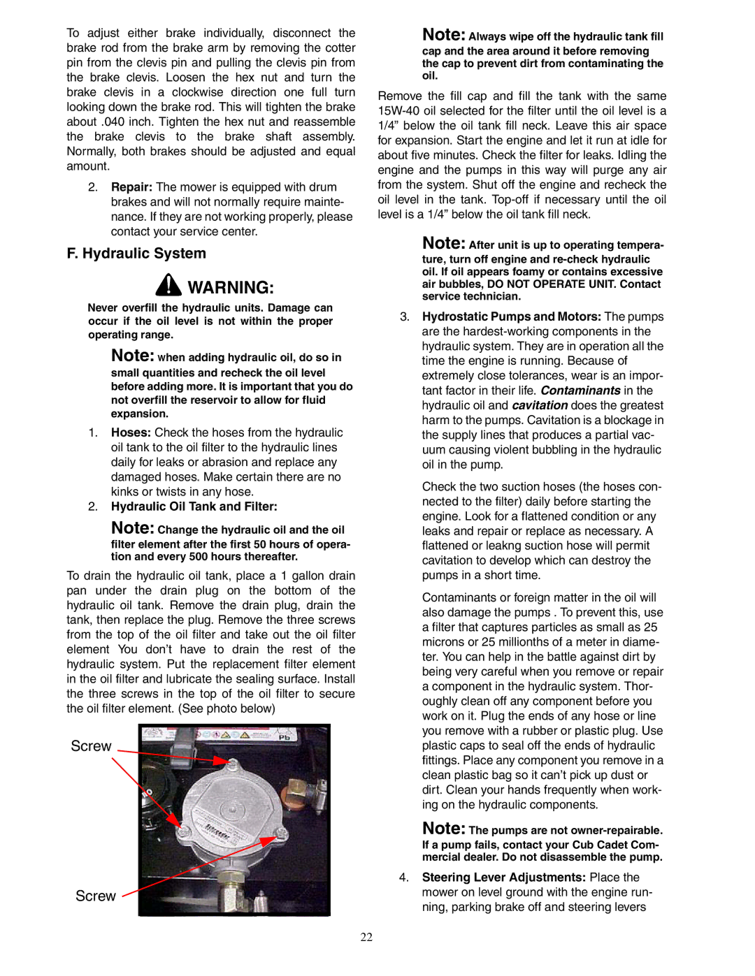
The 54-inch cutting deck offers a slightly larger option, ideal for larger residential properties or commercial applications. This model incorporates advanced features such as the Cub Cadet’s AeroForce technology, which enhances airflow to create a superior cut and reduces clumping yard debris. The durable construction of the 54-inch deck ensures longevity, paired with easy-to-adjust cutting height settings for versatile lawn care.
For those requiring even more power and coverage, the 60-inch cutting deck delivers outstanding performance on expansive lawns. It features a heavy-duty design that enhances durability and precision in cutting. With exceptional stability, this mower easily handles uneven terrain, providing a consistent blade height thanks to its advanced deck leveling system.
The 72-inch cutting deck is designed for professional landscapers and those with substantial property needs. This deck covers wide areas rapidly, reducing mowing time. It is engineered with a robust build, featuring reinforced blades that enhance cutting power. The 72-inch model also incorporates vibration-dampening technology, ensuring operator comfort during extended use.
Across all Cub Cadet models, key characteristics include ease of use with an intuitive dashboard, hydrostatic transmission for smooth maneuvering, and powerful engines that cater to the rigors of lawn care. The mowers also boast innovative safety features, including automatic blade brake systems and operator presence controls that require the operator to remain engaged while mowing.
With exceptional cutting technology, robust engineering, and varied sizes to meet different lawn demands, the Cub Cadet 48-inch, 54-inch, 60-inch, and 72-inch cutting decks stand as top choices for anyone seeking reliability and performance in lawn care. Whether for residential use or professional landscaping, these mowers deliver quality results with each pass.