Professional Tower UPS
PP1500/PP2200
User Manual |
SAFETY WARNINGS
(SAVE THESE INSTRUCTIONS)
This manual contains important safety instructions. Please read and follow all instructions carefully during installation and operation of the unit. Read this manual thoroughly before attempting to unpack, install, or operate your UPS.
This equipment can be operated by any individuals with no previous training. The
During the installation of this equipment it should be assured that the sum of the leakage currents of the UPS and the connected loads does not exceed 3.5mA.
Attention, hazardous through electric shock. Also with disconnection of this unit from the mains, hazardous voltage still may be accessible through supply from battery. The battery supply should be therefore disconnected in the plus and minus pole at the quick connectors of the battery when maintenance or service work inside the UPS is necessary.
Do not dispose of batteries in a fire, the battery may explode.
Do not open or mutilate the battery or batteries, released electrolyte is harmful to the skin and eyes.
INSTALLING YOUR UPS SYSTEM
UNPACKING
Inspect the UPS upon receipt. The box should contain the following:
UPS Unit x1; PowerPanel Business Edition Software Disk x1; Serial Interface Cable
HOW TO DETERMINE THE POWER REQUIREMENTS OF YOUR EQUIPMENT
1.Insure that the equipment plugged into the battery
2.If the power requirements of your equipment are listed in units other than
TO ESTIMATE POWER REQUIREMENTS
1. |
| Watts (W) x 2.0 = |
| VA or |
| Amps (A) x 120 = |
| VA |
2.Add the totals up for all pieces of equipment and multiply this total by 0.6 to calculate actual requirements. There are many factors that can affect the amount of power that your computer system will require. The total load that you will be placing on the
HARDWARE INSTALLATION GUIDE
1.Connect the equipment to your UPS outlets. Items such as copiers, laser printers, vacuums, space heaters, paper shredders, or other large electrical devices should not be connected to the UPS. Please assure that the total loads of your equipments must be less than the maximum total power load of your UPS.
2.Connect your UPS power cord into a
3.Press the UPS power button to turn it on. The “Power On” indicator will be illuminated in “Green”.
4.Install your optional software and accessories. To use the software, simply connect the enclosed serial interface cable to the serial port on the UPS and an open serial port on the computer.
BASIC OPERATION
FRONT PANEL DESCRIPTION
◆Power Switch
Press the ON/OFF button to turn the UPS on or off.
◆Test Switch
This UPS performs a
◆Battery Indicators
BATTERY
CAPACITY These indicators show a visual indication of the battery charge. If battery capacity is under 20%, no indicator LED will illuminate and the UPS starts beeping.
◆Load Level Indicators
LOAD
CAPACITY These LED indicators show a visual depiction of the UPS load. The load indicator LED will turn orange if the load is between 80 and 100%. If the load is under 20%, no indicator LED will illuminate.
◆Wiring Fault Indicator
This LED indicator will illuminate to warn the user that a wiring problem exits with the AC outlet, such as bad ground, miss ground or reversed wiring. If this is illuminated, the user is advised to disconnect all electrical equipment from the outlet and have an electrician check the outlet to insure proper wiring.
◆Using Battery Indicator
This illuminates during utility failure, indicating that the battery is supplying power to the
◆AVR Indicator
This LED indicates that the UPS is operating in automatic voltage regulation mode. When the LED is illuminated continuously, it indicates input
◆Power On Indicator
This LED is illuminated when the utility condition is normal and the UPS outlets are providing “clean power”, free of surges and spikes.
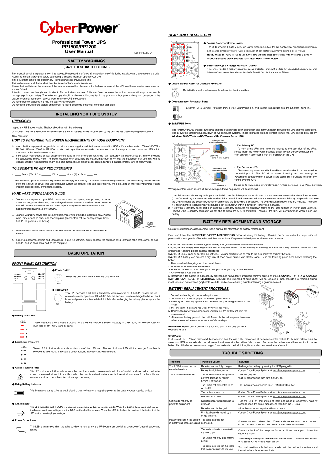
REAR PANEL DESCRIPTION
◆Backup Power for Critical Loads
The UPS provides 2 battery powered, surge protected outlets for the most critical connected equipments and insures temporary uninterrupted operation of connected equipments during a power failure.
NOTE: When the UPS is overloaded, the UPS will interrupt power supply to the other 6 battery outlets and leave these 2 outlets for critical loads uninterrupted.
◆Battery Backup and Surge Protection Outlets
This unit provides 6
◆Circuit Breaker Reset for Overload Protection
◆Communication Protection Ports
Ethernet
◆Serial/ USB Ports
The PP1500/PP2200 provides two serial and one USB ports to allow connection and communication between the UPS and two computers. This allows the simultaneous shutdown of two computer systems. These interfaces are also compatible with the UPS service provided by Windows 2000, Windows NT, Windows XP, Windows Server 2003.
1. The Primary PC
To control the UPS and make any change to the operation of the UPS, please install the PowerPanel Business Editon in your primary computer and then connect it to the Serial Port I or USB port of the UPS.
2. The Secondary PC
The secondary computer with PowerPanel installed should be connected to the serial port II. This PC will shutdown following the user settings in PowerPanel Software when a power failure occurs but it is unable to exhibit any control over the UPS.
Please go to www.cyberpowersystems.com for free download PowerPanel Software.
When power failure occurs, one of the following shutdown sequences will be executed:
1.If the Primary and Secondary serial ports are both in use: the Primary computer will start to count down (user controlled delay) for shutdown (User Control delay can be set in the PowerPanel Business Edition Recommended time is 5 minutes). Once the Primary computer is shutdown, the UPS will signal the Secondary computer and initiate the Secondary to shutdown. The UPS default shutdown time is 2 minutes. Therefore, it is recommended that Secondary computer is set to shutdown within 1 minute in PowerPanel Software.
2.If only the Secondary serial port is in use: the Secondary computer will shutdown following the user settings in PowerPanel Software. However, the Secondary computer will not able to signal the UPS to shutdown. Therefore, the UPS will only power off when it is in low battery.
BATTERY REPLACEMENT AND STORAGE
Contact your dealer or call the number in this manual for information on battery replacement.
Read and follow the IMPORTANT SAFETY INSTRUCTIONS before servicing the battery. Service the battery under the supervision of personnel knowledgeable of batteries and their precautions. Keep unauthorized personnel away from batteries.
CAUTION! Use only the specified type of battery. See your dealer for replacement batteries.
CAUTION! The battery may present the risk of electrical shock. Do not dispose of batteries in a fire, as it may explode. Follow all local ordinances regarding proper disposal of batteries.
CAUTION! Do not open or mutilate the batteries. Release electrolyte is harmful to the skin and eyes and may be toxic.
CAUTION! A battery can present a high risk of short circuit current and electric shock. Take the following precautions before replacing the battery:
1.Remove all watches, rings or other metal objects.
2.Only use tools with insulated handles.
3.DO NOT lay tools or other metal parts on top of battery or any battery terminals.
4.Wear rubber gloves and boots.
5.Determine if the battery is inadvertently grounded. If inadvertently grounded, remove source of ground. CONTACT WITH A GROUNDED BATTERY CAN RESULT IN ELECTRICAL SHOCK! The likelihood of such shock will be reduced if such grounds are removed during installation and maintenance (applicable to a UPS and a remote battery supply not having a grounded circuit).
BATTERY REPLACEMENT PROCEDURE:
1. | Turn off and unplug all connected equipments. |
| |
2. | Turn the UPS off and unplug it from the AC power source. |
| |
3. | Carefully turn the UPS upside down. Remove the 6 retaining screws and the |
| |
| cover. | (2) | |
4. | Disconnect the black and red wires from the battery set. | ||
(1) | |||
5. | Remove the battery protection cover and take out the battery set from the | ||
|
compartment.
6. Slide a new battery pack into the unit. Assemble the battery protection cover, cable, screws in the reverse sequence of above steps.
REMINDER: Recharge the unit for 4 – 8 hours to ensure the UPS performs
expected runtime(4)
(3)
STORAGE:
First turn off your UPS and disconnect its power cord from the wall outlet. Disconnect all cables connected to the UPS to avoid battery drain. To store your UPS for an extended period, cover it and store with the battery fully charged. Recharge the battery every three months to insure battery life. If the battery remains uncharged for an extended period of time, it may suffer permanent loss of capacity.
TROUBLE SHOOTING
Problem | Possible Cause | Solution | |
|
|
| |
The UPS does not perform | Batteries are not fully charged. | Recharge the battery by leaving the UPS plugged in. | |
expected runtime. |
|
| |
Battery is slightly worn out. | Contact CyberPower Systems at tech@cyberpowersystems.com. | ||
| |||
|
|
| |
The UPS will not turn on. | The on/off switch is designed to | Turn the UPS off. | |
| prevent damage by rapidly | Wait 10 seconds and then turn the UPS on. | |
| turning it off and on. |
| |
|
|
| |
| The unit is not connected to an | The unit must be connected to a 110/120v 60Hz outlet. | |
| AC outlet. |
| |
|
|
| |
| The battery is worn out. | Contact CyberPower Systems at tech@cyberpowersystems.com. | |
|
|
| |
| Mechanical problem. | Contact CyberPower Systems at tech@cyberpowersystems.com. | |
|
|
| |
Outlets do not provide | Circuit breaker is tripped due to | Turn the UPS off and unplug at least one piece of equipment. Wait 10 | |
power to equipment | overload | seconds, reset the circuit breaker and then turn the UPS on. | |
|
|
| |
| Batteries are discharged | Allow the unit to recharge for at least 4 hours. | |
|
|
| |
| Unit has been damaged by a | Contact CyberPower Systems at tech@cyberpowersystems.com. | |
| surge or spike. |
| |
|
|
| |
PowerPanel Business Edition | The serial cable is not | Connect the serial cable to the UPS unit and an open serial port on the back | |
is inactive (all icons are gray). | connected. | ||
of the computer. You must use the cable that came with the unit. | |||
|
| ||
|
|
| |
| The serial cable is connected to | Check the back of the computer for an additional serial port. Move the | |
| the wrong port. | ||
| cable to this port. | ||
|
| ||
|
|
| |
| The unit is not providing battery | Shutdown your computer and turn the UPS off. Wait 10 seconds and turn the | |
| power. | ||
| UPS back on. This should reset the unit. | ||
|
| ||
|
|
| |
| The serial cable is not the cable | You must use the cable that was included with the unit for the software and | |
| that was provided with the unit. | ||
| the unit to be able to communicate. | ||
|
| ||
|
|
|