CP685AVRLCD-G / CP825AVRLCD-G
User’s Manual
IMPORTANT SAFETY WARNINGS
(SAVE THESE INSTRUCTIONS)
This manual contains important safety instructions. Please read and follow all instructions carefully during installation and operation of the unit. Read this manual thoroughly before attempting to unpack, install, or operate your UPS.
CAUTION! To prevent the risk of fire or electric shock, install in a temperature and humidity controlled indoor area free of conductive contaminants. (Please see specifications for acceptable temperature and humidity range).
CAUTION! To reduce the risk of electric shock, do not remove the cover except to service the battery. There are no user serviceable parts inside except for battery.
CAUTION! Hazardous live parts inside can be energized by the battery even when the AC input power is disconnected.
CAUTION! The UPS must be connected to an AC power outlet with fuse or circuit breaker protection. Do not plug into an outlet that is not grounded. If you need to
CAUTION! To avoid electric shock, turn off the unit and unplug it from the AC power source before servicing the battery or installing a computer component.
CAUTION! To reduce the risk of fire, connect only to a circuit provided with 20 amperes maximum branch circuit over current protection in accordance with the National Electric Code, ANSI/NFPA 70.
DO NOT USE FOR MEDICAL OR LIFE SUPPORT EQUIPMENT! CyberPower Systems does not sell products for life support or medical applications. DO NOT use in any circumstance that would affect operation, safety of any life support equipment, any medical applications or patient care.
DO NOT USE WITH OR NEAR AQUARIUMS! To reduce the risk of fire or electric shock, do not use with or near an aquarium. Condensation from the aquarium can cause the unit to short out.
INSTALLING YOUR UPS SYSTEM
UNPACKING
Inspect the UPS upon receipt. The box should contain the following:
(1)UPS unit; (1) User’s manual; (1) PowerPanel® Personal Edition software CD; (1) USB device cable; (1) Telephone cable; (1) Warranty registration card; (1) Coaxial Cable
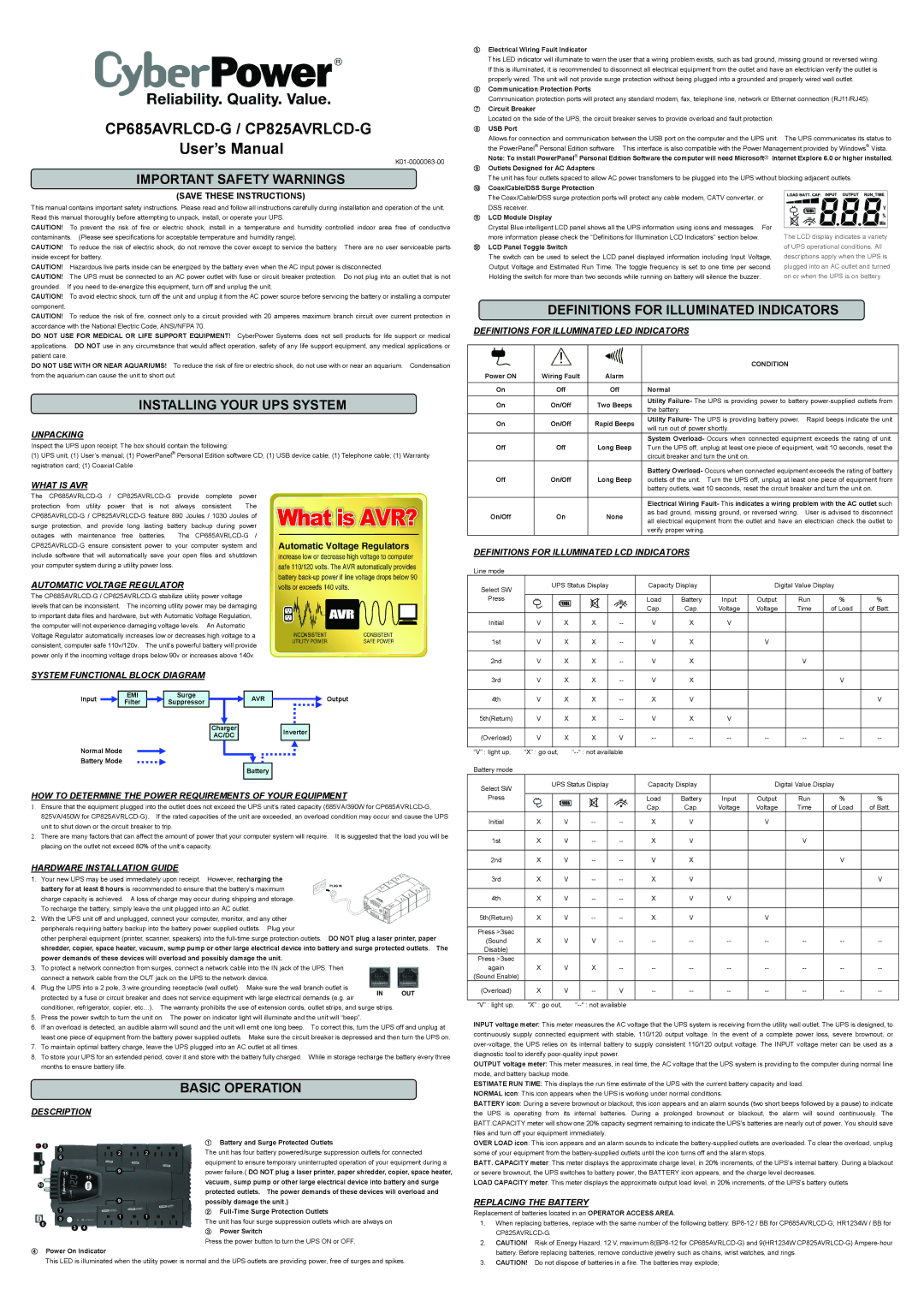
WHAT IS AVR
The
AUTOMATIC VOLTAGE REGULATOR
The
SYSTEM FUNCTIONAL BLOCK DIAGRAM
Input | EMI |
| Surge |
|
| AVR |
|
| Output |
Filter |
| Suppressor |
|
|
|
| |||
| |||||||||
|
|
|
|
|
|
|
|
|
|
|
|
|
| Charger |
|
|
| Inverter |
|
|
|
|
| AC/DC |
|
|
|
| |
|
|
|
|
|
|
|
|
|
|
Normal Mode
Battery Mode
Battery
HOW TO DETERMINE THE POWER REQUIREMENTS OF YOUR EQUIPMENT
1.Ensure that the equipment plugged into the outlet does not exceed the UPS unit’s rated capacity (685VA/390W for
2.There are many factors that can affect the amount of power that your computer system will require. It is suggested that the load you will be placing on the outlet not exceed 80% of the unit’s capacity.
1.Your new UPS may be used immediately upon receipt. However, recharging the battery for at least 8 hours is recommended to ensure that the battery’s maximum charge capacity is achieved. A loss of charge may occur during shipping and storage. To recharge the battery, simply leave the unit plugged into an AC outlet.
2.With the UPS unit off and unplugged, connect your computer, monitor, and any other peripherals requiring battery backup into the battery power supplied outlets. Plug your
other peripheral equipment (printer, scanner, speakers) into the
3.To protect a network connection from surges, connect a network cable into the IN jack of the UPS. Then connect a network cable from the OUT jack on the UPS to the network device.
4.Plug the UPS into a 2 pole, 3 wire grounding receptacle (wall outlet). Make sure the wall branch outlet is protected by a fuse or circuit breaker and does not service equipment with large electrical demands (e.g. air conditioner, refrigerator, copier, etc…). The warranty prohibits the use of extension cords, outlet strips, and surge strips.
5.Press the power switch to turn the unit on. The power on indicator light will illuminate and the unit will “beep”.
6.If an overload is detected, an audible alarm will sound and the unit will emit one long beep. To correct this, turn the UPS off and unplug at least one piece of equipment from the battery power supplied outlets. Make sure the circuit breaker is depressed and then turn the UPS on.
7.To maintain optimal battery charge, leave the UPS plugged into an AC outlet at all times.
8.To store your UPS for an extended period, cover it and store with the battery fully charged. While in storage recharge the battery every three months to ensure battery life.
BASIC OPERATION
DESCRIPTION
①Battery and Surge Protected Outlets
The unit has four battery powered/surge suppression outlets for connected equipment to ensure temporary uninterrupted operation of your equipment during a power failure.( DO NOT plug a laser printer, paper shredder, copier, space heater, vacuum, sump pump or other large electrical device into battery and surge protected outlets. The power demands of these devices will overload and possibly damage the unit.)
②
The unit has four surge suppression outlets which are always on
③Power Switch
Press the power button to turn the UPS ON or OFF.
④Power On Indicator
This LED is illuminated when the utility power is normal and the UPS outlets are providing power, free of surges and spikes.
⑤Electrical Wiring Fault Indicator
This LED indicator will illuminate to warn the user that a wiring problem exists, such as bad ground, missing ground or reversed wiring. If this is illuminated, it is recommended to disconnect all electrical equipment from the outlet and have an electrician verify the outlet is properly wired. The unit will not provide surge protection without being plugged into a grounded and properly wired wall outlet.
⑥Communication Protection Ports
Communication protection ports will protect any standard modem, fax, telephone line, network or Ethernet connection (RJ11/RJ45).
⑦Circuit Breaker
Located on the side of the UPS, the circuit breaker serves to provide overload and fault protection.
⑧USB Port
Allows for connection and communication between the USB port on the computer and the UPS unit. The UPS communicates its status to
the PowerPanel® Personal Edition software. This interface is also compatible with the Power Management provided by Windows® Vista.
Note: To install PowerPanel® Personal Edition Software the computer will need Microsoft○R Internet Explore 6.0 or higher installed.
⑨Outlets Designed for AC Adapters
The unit has four outlets spaced to allow AC power transfomers to be plugged into the UPS without blocking adjacent outlets.
⑩Coax/Cable/DSS Surge Protection
The Coax/Cable/DSS surge protection ports will protect any cable modem, CATV converter, or DSS receiver.
⑪ | LCD Module Display |
|
| Crystal Blue intelligent LCD panel shows all the UPS information using icons and messages. For |
|
| more information please check the “Definitions for Illumination LCD Indicators” section below. | The LCD display indicates a variety |
⑫ | LCD Panel Toggle Switch | of UPS operational conditions. All |
| The switch can be used to select the LCD panel displayed information including Input Voltage, | descriptions apply when the UPS is |
| Output Voltage and Estimated Run Time. The toggle frequency is set to one time per second. | plugged into an AC outlet and turned |
| Holding the switch for more than two seconds while running on battery will silence the buzzer. | on or when the UPS is on battery. |
DEFINITIONS FOR ILLUMINATED INDICATORS
DEFINITIONS FOR ILLUMINATED LED INDICATORS
|
|
| CONDITION | |
Power ON | Wiring Fault | Alarm |
| |
|
|
|
| |
On | Off | Off | Normal | |
On | On/Off | Two Beeps | Utility Failure- The UPS is providing power to battery | |
the battery. | ||||
|
|
| ||
On | On/Off | Rapid Beeps | Utility Failure- The UPS is providing battery power. Rapid beeps indicate the unit | |
will run out of power shortly. | ||||
|
|
| ||
|
|
| System Overload- Occurs when connected equipment exceeds the rating of unit. | |
Off | Off | Long Beep | Turn the UPS off, unplug at least one piece of equipment, wait 10 seconds, reset the | |
|
|
| circuit breaker and turn the unit on. | |
|
|
| Battery Overload- Occurs when connected equipment exceeds the rating of battery | |
Off | On/Off | Long Beep | outlets of the unit. Turn the UPS off, unplug at least one piece of equipment from | |
|
|
| battery outlets, wait 10 seconds, reset the circuit breaker and turn the unit on. | |
|
|
|
| |
|
|
| Electrical Wiring Fault- This indicates a wiring problem with the AC outlet such | |
On/Off | On | None | as bad ground, missing ground, or reversed wiring. User is advised to disconnect | |
all electrical equipment from the outlet and have an electrician check the outlet to | ||||
|
|
| ||
|
|
| verify proper wiring. |
DEFINITIONS FOR ILLUMINATED LCD INDICATORS
Line mode
Select SW | UPS Status Display |
| Capacity Display |
| Digital Value Display |
| ||||||||
|
|
|
|
|
|
|
|
|
|
|
|
|
| |
Press |
|
|
|
|
|
|
| Load | Battery | Input | Output | Run | % | % |
|
|
|
|
|
|
|
| Cap. | Cap. | Voltage | Voltage | Time | of Load | of Batt. |
Initial | V |
| X |
| X |
| V | X | V |
|
|
|
| |
|
|
|
|
|
|
|
|
|
|
|
|
|
|
|
1st | V |
| X |
| X |
| V | X |
| V |
|
|
| |
|
|
|
|
|
|
|
|
|
|
|
|
|
|
|
2nd | V |
| X |
| X |
| V | X |
|
| V |
|
| |
|
|
|
|
|
|
|
|
|
|
|
|
|
|
|
3rd | V |
| X |
| X |
| V | X |
|
|
| V |
| |
|
|
|
|
|
|
|
|
|
|
|
|
|
|
|
4th | V |
| X |
| X |
| X | V |
|
|
|
| V | |
|
|
|
|
|
|
|
|
|
|
|
|
|
|
|
5th(Return) | V |
| X |
| X |
| V | X | V |
|
|
|
| |
|
|
|
|
|
|
|
|
|
|
|
|
|
|
|
(Overload) | V |
| X |
| X |
| V | |||||||
|
|
|
|
|
|
|
|
|
|
|
|
|
| |
“V” : light up, | “X” : go out, |
|
|
|
|
|
|
|
| |||||
Battery mode |
|
|
|
|
|
|
|
|
|
|
|
|
|
|
Select SW | UPS Status Display |
| Capacity Display |
| Digital Value Display |
| ||||||||
|
|
|
|
|
|
|
|
|
|
|
|
|
| |
Press |
|
|
|
|
|
|
| Load | Battery | Input | Output | Run | % | % |
|
|
|
|
|
|
|
| Cap. | Cap. | Voltage | Voltage | Time | of Load | of Batt. |
Initial | X |
| V |
|
| X | V |
| V |
|
|
| ||
|
|
|
|
|
|
|
|
|
|
|
|
|
|
|
1st | X |
| V |
|
| X | V |
|
| V |
|
| ||
|
|
|
|
|
|
|
|
|
|
|
|
|
|
|
2nd | X |
| V |
|
| V | X |
|
|
| V |
| ||
|
|
|
|
|
|
|
|
|
|
|
|
|
|
|
3rd | X |
| V |
|
| X | V |
|
|
|
| V | ||
|
|
|
|
|
|
|
|
|
|
|
|
|
|
|
4th | X |
| V |
|
| X | V | V |
|
|
|
| ||
|
|
|
|
|
|
|
|
|
|
|
|
|
|
|
5th(Return) | X |
| V |
|
| X | V |
| V |
|
|
| ||
|
|
|
|
|
|
|
|
|
|
|
|
|
|
|
Press >3sec |
|
|
|
|
|
|
|
|
|
|
|
|
|
|
(Sound | X |
| V |
| V |
| ||||||||
Disable) |
|
|
|
|
|
|
|
|
|
|
|
|
|
|
Press >3sec |
|
|
|
|
|
|
|
|
|
|
|
|
|
|
again | X |
| V |
| X |
| ||||||||
(Sound Enable) |
|
|
|
|
|
|
|
|
|
|
|
|
|
|
(Overload) | X |
| V |
|
| V | ||||||||
|
|
|
|
|
|
|
|
|
|
|
|
|
| |
“V” : light up, | “X” : go out, |
|
|
|
|
|
|
|
| |||||
INPUT voltage meter: This meter measures the AC voltage that the UPS system is receiving from the utility wall outlet. The UPS is designed, to continuously supply connected equipment with stable, 110/120 output voltage. In the event of a complete power loss, severe brownout, or
OUTPUT voltage meter: This meter measures, in real time, the AC voltage that the UPS system is providing to the computer during normal line mode, and battery backup mode.
ESTIMATE RUN TIME: This displays the run time estimate of the UPS with the current battery capacity and load.
NORMAL icon: This icon appears when the UPS is working under normal conditions.
BATTERY icon: During a severe brownout or blackout, this icon appears and an alarm sounds (two short beeps followed by a pause) to indicate the UPS is operating from its internal batteries. During a prolonged brownout or blackout, the alarm will sound continuously. The BATT.CAPACITY meter will show one 20% capacity segment remaining to indicate the UPS's batteries are nearly out of power. You should save files and turn off your equipment immediately.
OVER LOAD icon: This icon appears and an alarm sounds to indicate the
BATT. CAPACITY meter: This meter displays the approximate charge level, in 20% increments, of the UPS’s internal battery. During a blackout or severe brownout, the UPS switches to battery power, the BATTERY icon appears, and the charge level decreases.
LOAD CAPACITY meter: This meter displays the approximate output load level, in 20% increments, of the UPS’s battery outlets
REPLACING THE BATTERY
Replacement of batteries located in an OPERATOR ACCESS AREA.
1.When replacing batteries, replace with the same number of the following battery:
2.CAUTION! Risk of Energy Hazard, 12 V, maximum
3.CAUTION! Do not dispose of batteries in a fire. The batteries may explode;