Manuals
/
CyberPower Systems
/
Computer Equipment
/
Power Supply
CyberPower Systems
CPS900AVR Description, Guaranteed Uninterruptible Power System, Power Switch
Models:
CPS900AVR
1
3
15
15
Download
15 pages
26.38 Kb
1
2
3
4
5
6
7
8
Troubleshooting
Install
Alarm
Power On Indicator
Warranty
Replacing The Battery
Testing Your Ups System
Powerpanel Plus Main Menu
Page 3
Image 3
Page 2
Page 4
Page 3
Image 3
Page 2
Page 4
Contents
User Manual for
ADDITIONAL INSTALLATION TIPS CAN BE FOUND AT
and PowerPanel Plus Software User Manual
CPS900AVR
Determining Power Requirements
IMPORTANT SAFETY INSTRUCTIONS SAVE THESE INSTRUCTIONS
TABLE OF CONTENTS
LED Indicators
Guaranteed Uninterruptible Power System
HOW TO DETERMINE THE POWER REQUIREMENTS OF YOUR EQUIPMENT
CPS900AVR
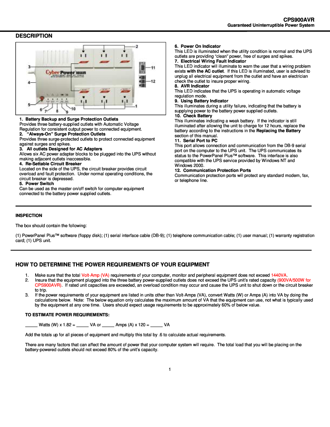
DESCRIPTION
HARDWARE INSTALLATION GUIDE
12. Double-click on Add/Remove Programs
POWERPANEL PLUS SOFTWARE INSTALLATION GUIDE
FOR WINDOWS 95/98/Me
FOR WINDOWS NT
OVERVIEW
POWERPANEL PLUS SOFTWARE USER MANUAL
POWERPANEL PLUS MAIN MENU
POWERPANEL PLUS MAIN WINDOW DESCRIPTION
7. Cancel Exits the window without saving changes
POWERPANEL PLUS SETUP WINDOW
9. Advance This button opens the Advanced Setup Window
POWERPANEL PLUS ADVANCED SETUP
If you are using PowerPanel Plus
POWERPANEL PLUS SCHEDULE MENU
POWERPANEL PLUS LOG MENU
TESTING YOUR UPS SYSTEM
Using
DEFINITIONS FOR ILLUMINATED LED INDICATORS
Power
Wiring
Solution
TROUBLESHOOTING
SPECIFICATIONS
Problem
Load Watts
REPLACING THE BATTERY
TO REPLACE THE BATTERY
EXPECTED RUNTIME IN MINUTES
Limited Warranty And Power Control Guarantee
LIMITED WARRANTY
POWER CONTROL GUARANTEE
CONDITIONS COMMON TO THE LIMITED
WARRANTY AND THE POWER CONTROL GUARANTEE
The Limited Warranty and the Power Control Guarantee are intended to exclusive rights and remedies and replace any other rights, to the extent allowed by law
Email sales@cyberpowersystems.com
For more information, contact us at CyberPower Systems USA, Inc
FCC Notice
5555 12th Avenue East Suite Shakopee, MN Tel 952 Fax 952
Top
Page
Image
Contents