6.DACK# is used in conjunction with DRQ#. If INT# is used to indicate that at least one bit is set in the DRQ# register, then DACK# remains unused. DACK# is not required for Astoria to function.

7.INT#, DRQ#, and DACK# are in GVVDQ power domain. Therefore, pull up the input pin DACK# to GVDDQ using a 10k resistor, if it is not used.

8.All unused inputs and input or output pins on the P-port are tied to a valid logic level (HIGH for lowest leakage) through a 10k resistor. Use a single resistor for all unused pins. When pulling HIGH, the unused pins are tied to the appropriate power domain, in this case, PVDDQ or GVDDQ.

Refer to the Pin Assignments table in the data sheet for more details on pin configuration for each P-port interface mode and their corresponding power domains.

9.The INT# and DRQ# signals float when Astoria is in Standby state. These signals are active low. As a result, a pull up resistor must be connected to these signals to prevent the P-port processor from receiving any false interrupts.

10.In the PNAND Interface Mode, external pull up is not required for the R/B# signal. R/B# signal is not an open drain or collector output.

S-Port

1.Use SD_D[3]/SD2_D[3] or GPIO[0]/GPIO[1] to detect cards on Astoria. If SD_D[3]/SD2_D[3] is used, then it must be pulled down using a 470 kΩ resistor.

2.Treat the SD_CLK signal as a high speed signal switching at a maximum of 48 MHz to determine the appropriate signal integrity precautions.

3.If you are designing an application supporting SD/MMC and CE-ATA, follow the trace length restrictions.

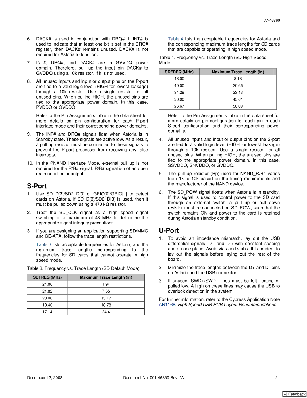
Table 3 lists acceptable frequencies for Astoria, and the maximum trace lengths corresponding to the frequencies for SD cards that cannot operate in high speed mode.

Table 3. Frequency vs. Trace Length (SD Default Mode)

SDFREQ (MHz)

Maximum Trace Length (in)

24.00

1.94


21.82

7.55


20.00

13.17


18.46

18.78


17.14

24.4


AN46860

Table 4 lists the acceptable frequencies for Astoria and the corresponding maximum trace lengths for SD cards that are capable of operating in high speed mode.

Table 4. Frequency vs. Trace Length (SD High Speed Mode)

SDFREQ (MHz)

Maximum Trace Length (in)

48.00

8.18


40.00

20.66


34.29

33.13


30.00

45.61


26.67

58.08


Refer to the Pin Assignments table in the data sheet for more details on pin configuration for each pin in each S-port configuration and their corresponding power domains.

4.All unused inputs and input or output pins on the S-port are tied to a valid logic level (HIGH for lowest leakage) through a 10k resistor. Use a single resistor for all unused pins. When pulling HIGH, the unused pins are tied to the appropriate power domain, in this case, SSVDDQ, SNVDDQ, or GVDDQ.

5.The pull up resistor (Rp) used for NAND_R/B# varies from 1k to 10k based on the timing requirements and the manufacturer of the NAND device.

6.The SD_POW signal floats when Astoria is in standby. If this signal is used to control power to the SD card through an external switch, a pull up or pull down resistor must be connected on SD_POW, such that the switch remains ON and power to the card is retained during Astoria’s standby condition.

U-Port

1.To avoid an impedance mismatch, lay out the USB differential signals (D+ and D-) with constant spacing and on one plane. Avoid vias and stubs. It is prudent to lay out the signals before laying out the rest of the board.

2.Minimize the trace lengths between the D+ and D- pins on Astoria and the USB connector.

3.If unused, SWD+/SWD– lines must be left floating or pulled low. A high on these lines may cause the USB to overlook detection in the system.

For further information, refer to the Cypress Application Note AN1168, High Speed USB PCB Layout Recommendations.

December 12, 2008

Document No. 001-46860 Rev. *A

2

[+] Feedback

Page 2
Image 2
Cypress AN46860 manual Sdfreq MHz Maximum Trace Length

AN46860 specifications

The Cypress AN46860 is a versatile and high-performance microcontroller that belongs to the PSoC (Cypress's Programmable System-on-Chip) family. This device is designed to cater to the demands of various embedded applications, providing developers with a unique blend of programmable analog and digital resources. The AN46860 is particularly well-suited for applications in automotive, industrial, and consumer electronics due to its robust feature set and reliable performance.

One of the standout features of the AN46860 is its flexible architecture. The microcontroller integrates a 32-bit ARM Cortex-M4 processor, which allows for efficient processing and handling of complex tasks. With clock speeds reaching up to 100 MHz, the AN46860 is capable of executing multiple instructions in parallel, significantly increasing its computational capabilities.

Another significant advantage of the AN46860 is its wide range of programmable analog and digital peripherals. The device includes various analog components, such as operational amplifiers, comparators, and high-resolution ADCs (Analog-to-Digital Converters). These components enable precise signal processing, making the microcontroller ideal for applications that require real-time data acquisition and conversion.

The digital side of the AN46860 boasts ample connectivity options, including multiple GPIOs, UART, SPI, I2C, and PWM, enabling seamless communication with other devices and peripherals. This makes it easier for developers to integrate the microcontroller into existing systems or to create new, innovative designs.

One of the highlights of the AN46860 is its programmability. The PSoC architecture allows developers to tailor the hardware functionality through software, a feature that can significantly reduce development time and costs. The device supports the Cypress PSoC Creator Integrated Development Environment (IDE), which provides a user-friendly interface and a rich library of pre-defined components, enabling developers to drag-and-drop their way to a custom solution.

Additionally, the AN46860 features a built-in bootloader to facilitate firmware updates and enhancements, ensuring that applications can be easily upgraded in the field. It also offers low-power modes that help extend battery life in portable applications, making it an attractive choice for energy-conscious designs.

In summary, the Cypress AN46860 is a powerful microcontroller with a blend of programmable analog and digital features, making it highly adaptable for various applications. Its combination of a robust processing core, extensive peripheral support, and flexibility through software programmability ensures that it meets the needs of today’s demanding technology landscape.