
CY7C1020BN specifications
The Cypress CY7C1020BN is a high-performance SRAM (Static Random Access Memory) device that is particularly well-suited for high-speed applications requiring fast access times and low power consumption. This 1 Megabit (1Mbit) SRAM is organized as 128K words by 8 bits, providing a total storage capacity that is ideal for embedded systems, networking equipment, and other devices that demand rapid data processing capabilities.One of the standout features of the CY7C1020BN is its access time of 10 ns to 15 ns, allowing for swift data read and write operations. This speed is critical in environments where timing is essential, such as telecommunications and computing applications. The device fully supports asynchronous read and write cycles, leading to efficient performance without the need for complex control logic.
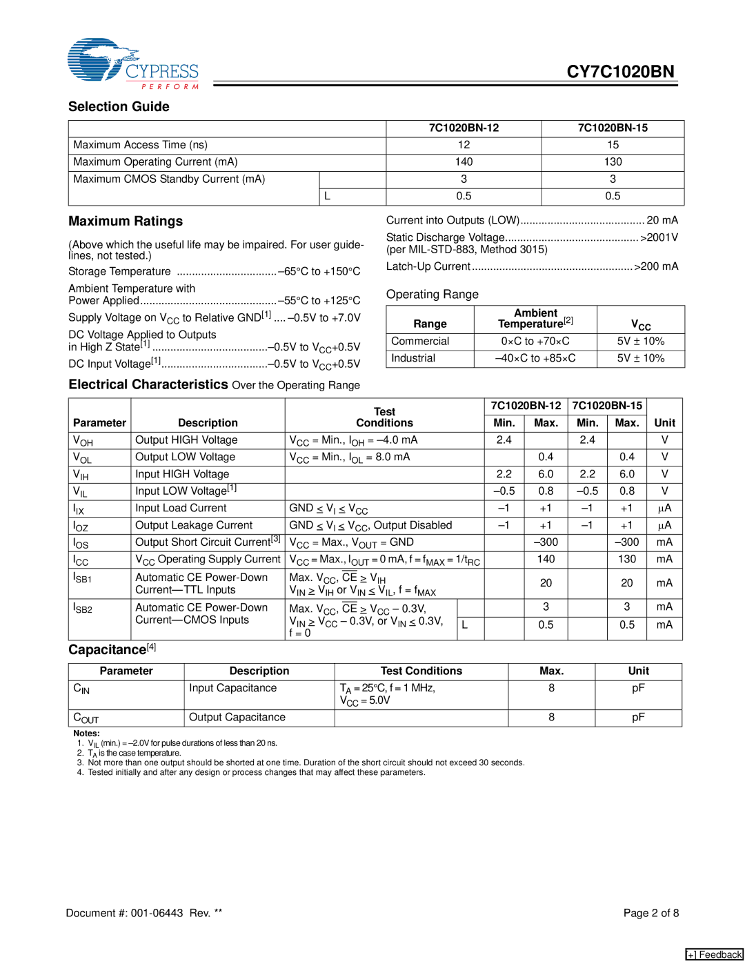
The CY7C1020BN utilizes a CMOS (Complementary Metal-Oxide-Semiconductor) technology which contributes to its low power consumption profile. It operates at a voltage of 2.7V to 5.5V, making it versatile for various system designs. The device boasts a low standby current of 1 µA, a significant advantage in battery-operated applications where power savings are crucial.
Additionally, the CY7C1020BN is designed for ease of use, featuring simple interfacing options that allow for seamless integration into existing designs. It operates using standard asynchronous control signals, making it compatible with a wide range of microcontrollers and FPGAs.
In terms of reliability, the CY7C1020BN is built to endure various environmental conditions and has a solid reputation for robust performance over time. Features such as an extended temperature range and guaranteed write endurance enhance its durability in demanding applications.
The package options for the CY7C1020BN include various pin configurations, accommodating different board layouts and space constraints. This flexibility makes it an attractive choice for designers seeking to optimize their space without compromising on performance.
In summary, the Cypress CY7C1020BN is an excellent choice for applications requiring high-speed, low-power static RAM. With its fast access times, low power consumption, versatile voltage range, and compatibility with standard control signals, it continues to be a preferred memory solution in various high-performance systems. Whether in communication devices, industrial equipment, or consumer electronics, it provides reliability and efficiency that engineers can count on.