Model No.: | User’s Manual |
Ⅰ.Introduction
The
Ⅱ. Mounting configuration of DCS-50
(D)
(E)
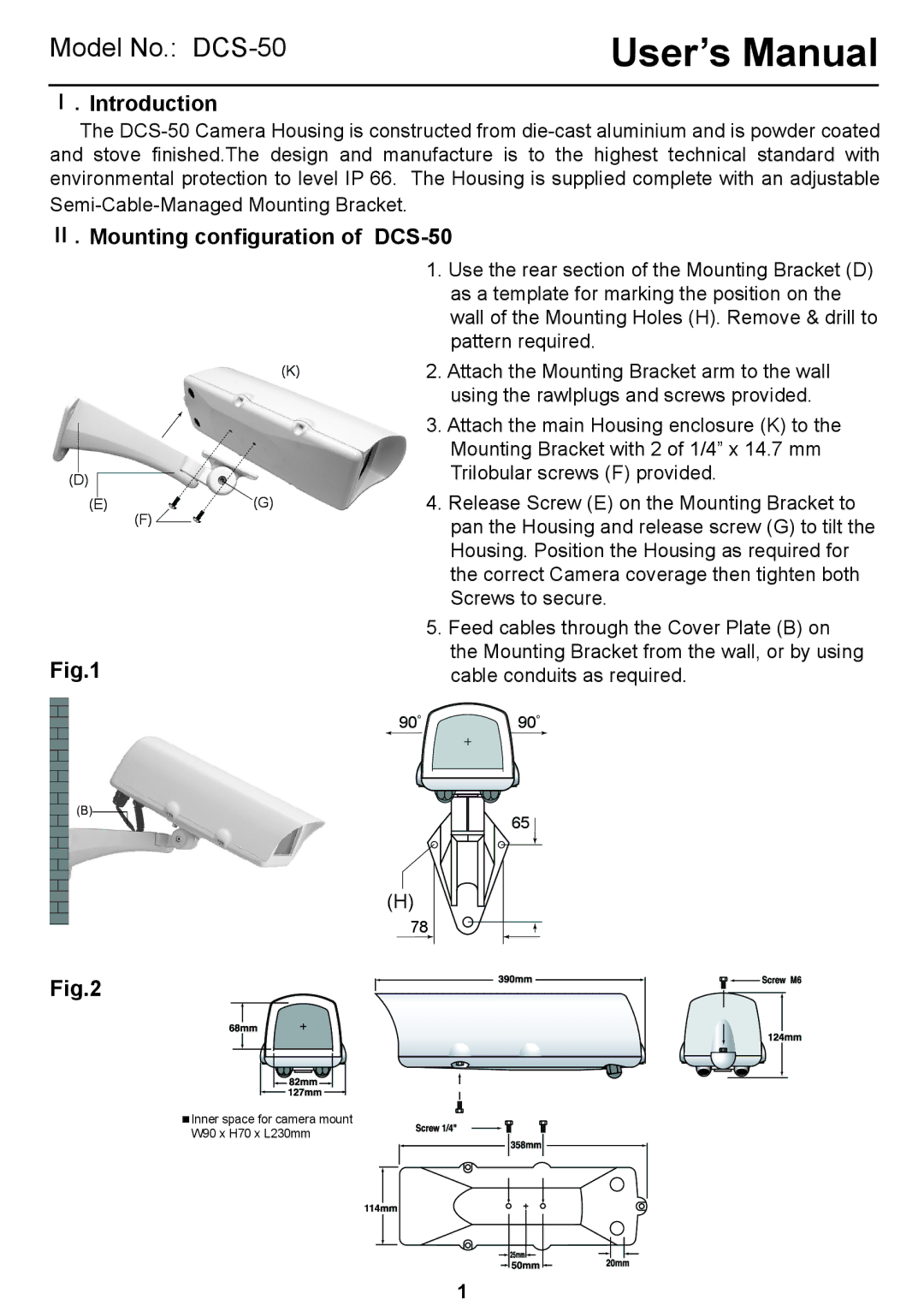
Fig.1
(B)
Fig.2
1.Use the rear section of the Mounting Bracket (D) as a template for marking the position on the wall of the Mounting Holes (H). Remove & drill to pattern required.
(K)2. Attach the Mounting Bracket arm to the wall using the rawlplugs and screws provided.
| 3. Attach the main Housing enclosure (K) to the |
| Mounting Bracket with 2 of 1/4” x 14.7 mm |
| Trilobular screws (F) provided. |
(G) | 4. Release Screw (E) on the Mounting Bracket to |
(F) | pan the Housing and release screw (G) to tilt the |
| |
| Housing. Position the Housing as required for |
| the correct Camera coverage then tighten both |
| Screws to secure. |
5.Feed cables through the Cover Plate (B) on the Mounting Bracket from the wall, or by using cable conduits as required.
90° 90°
65 ![]()
(H)
78
![]() Inner space for camera mount W90 x H70 x L230mm
Inner space for camera mount W90 x H70 x L230mm
1