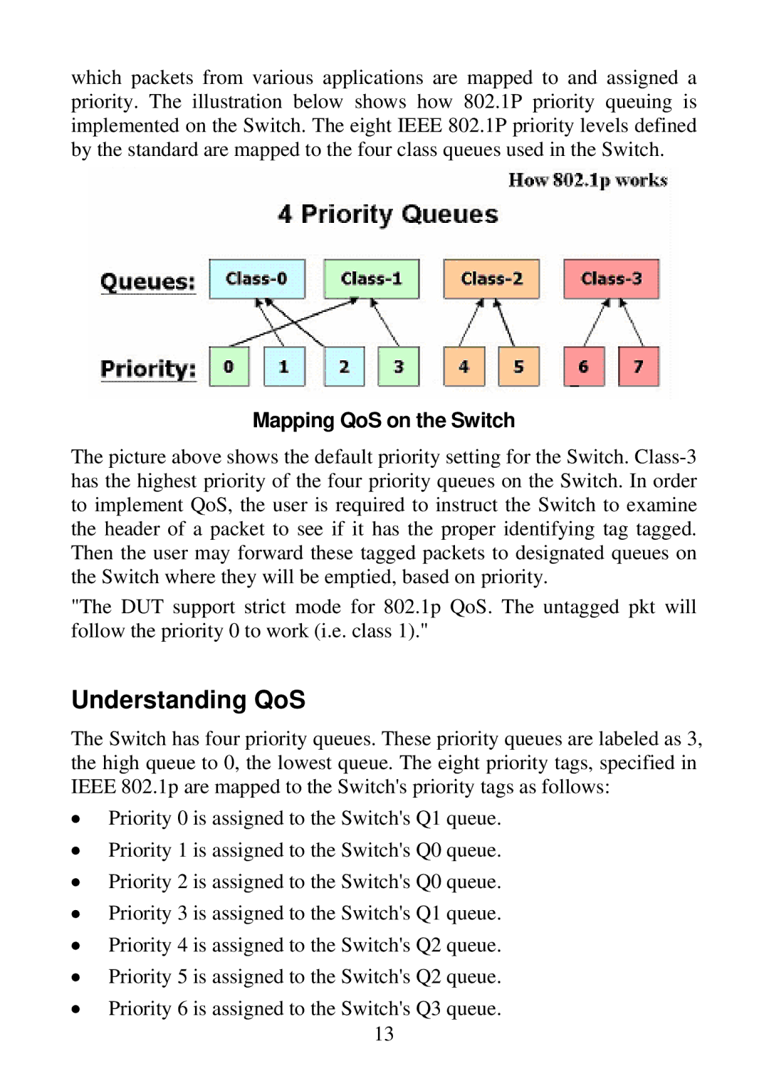
which packets from various applications are mapped to and assigned a priority. The illustration below shows how 802.1P priority queuing is implemented on the Switch. The eight IEEE 802.1P priority levels defined by the standard are mapped to the four class queues used in the Switch.
Mapping QoS on the Switch
The picture above shows the default priority setting for the Switch.
"The DUT support strict mode for 802.1p QoS. The untagged pkt will follow the priority 0 to work (i.e. class 1)."
Understanding QoS
The Switch has four priority queues. These priority queues are labeled as 3, the high queue to 0, the lowest queue. The eight priority tags, specified in IEEE 802.1p are mapped to the Switch's priority tags as follows:
•Priority 0 is assigned to the Switch's Q1 queue.
•Priority 1 is assigned to the Switch's Q0 queue.
•Priority 2 is assigned to the Switch's Q0 queue.
•Priority 3 is assigned to the Switch's Q1 queue.
•Priority 4 is assigned to the Switch's Q2 queue.
•Priority 5 is assigned to the Switch's Q2 queue.
•Priority 6 is assigned to the Switch's Q3 queue. 13