SAFETY PRECAUTIONS
CAUTION : Do not attempt to modify this product in any way. Unau- thorized modifications will not only void the warranty, but may lead to your being liable for any resulting property damage or user injury.
Service work should be performed only after you are thoroughly familiar with all of the following safety checks and servicing
SAFETY CHECKS
After the original service problem has been corrected, a check should be made of the following:
SUBJECT : FIRE & SHOCK HAZARD
1.Be sure that all components are positioned in such a way as to avoid possibility of adjacent component shorts. This is especially important on those chassis which are transported to and from the repair shop.
2.Never release a repair unless all protective devices such as
3.Soldering must be inspected to discover possible cold solder joints, frayed leads, damaged insulation (including A.C. cord), solder splashes or sharp solder points. Be certain to remove all loose
4.Check for physical evidence of damage or deterioration to parts and components, and replace if necessary follow original layout, lead length and dress.
5.No leads or components should touch a receiving tube or a resistor rated at 1 watt or more. Lead tension around protruding metal
6.All critical components such as fuses, flameproof resistors,
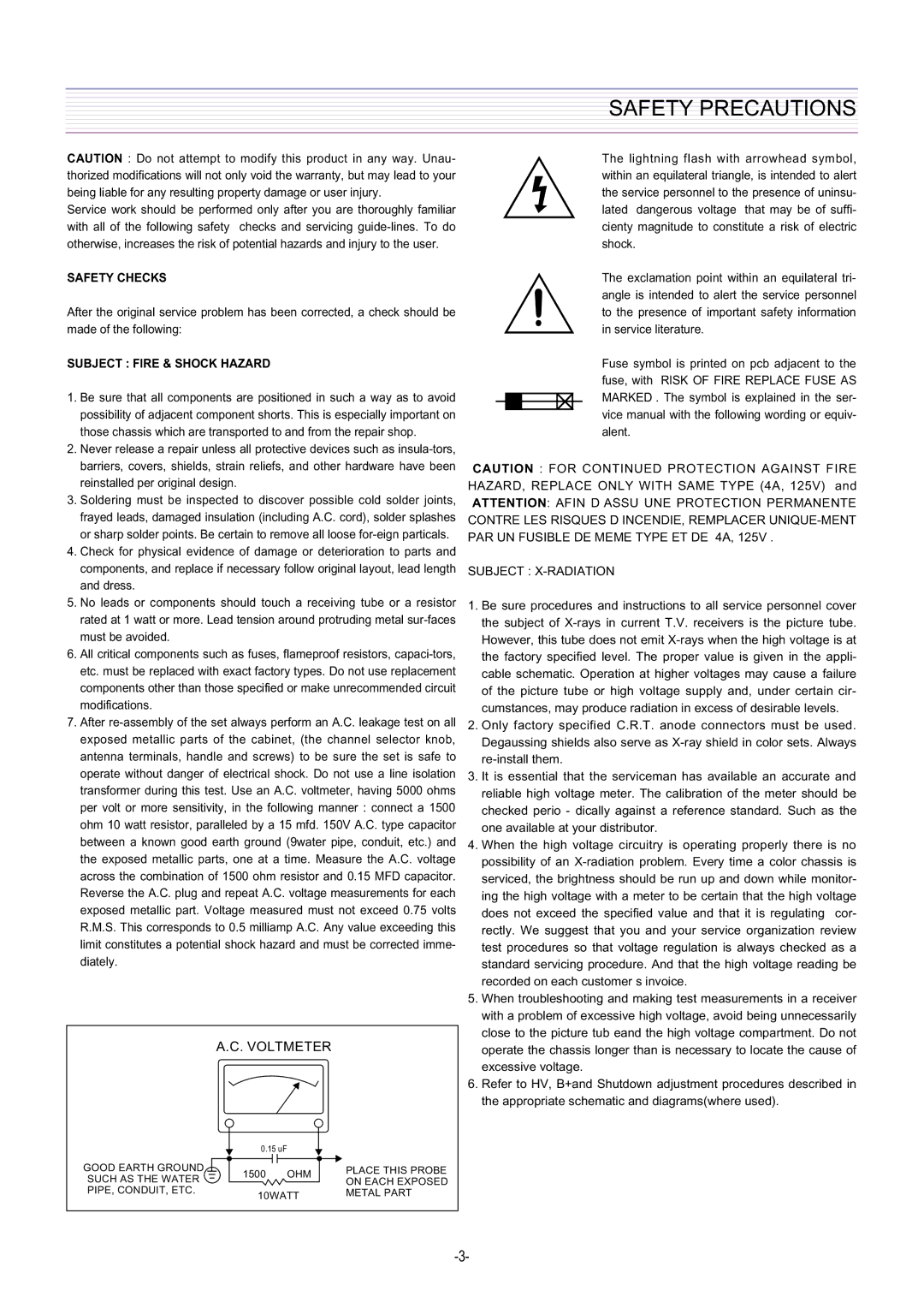
7.After
A.C. VOLTMETER
GOOD EARTH GROUND |
|
|
|
|
| 0.15 uF |
| PLACE THIS PROBE |
|
|
|
| |||||
|
|
|
|
| 1500 OHM |
| ||
|
|
|
|
|
| |||
SUCH AS THE WATER |
|
|
|
|
| ON EACH EXPOSED | ||
|
|
|
|
|
| |||
PIPE, CONDUIT, ETC. |
|
|
|
| 10WATT |
| METAL PART | |
The lightning flash with arrowhead symbol, within an equilateral triangle, is intended to alert the service personnel to the presence of uninsu- lated dangerous voltage that may be of suffi- cienty magnitude to constitute a risk of electric shock.
The exclamation point within an equilateral tri- angle is intended to alert the service personnel to the presence of important safety information in service literature.
Fuse symbol is printed on pcb adjacent to the fuse, with RISK OF FIRE REPLACE FUSE AS MARKED . The symbol is explained in the ser- vice manual with the following wording or equiv- alent.
CAUTION : FOR CONTINUED PROTECTION AGAINST FIRE HAZARD, REPLACE ONLY WITH SAME TYPE (4A, 125V) and
ATTENTION: AFIN D ASSU UNE PROTECTION PERMANENTE CONTRE LES RISQUES D INCENDIE, REMPLACER
SUBJECT : X-RADIATION
1.Be sure procedures and instructions to all service personnel cover the subject of
2.Only factory specified C.R.T. anode connectors must be used. Degaussing shields also serve as
3.It is essential that the serviceman has available an accurate and reliable high voltage meter. The calibration of the meter should be checked perio - dically against a reference standard. Such as the one available at your distributor.
4.When the high voltage circuitry is operating properly there is no possibility of an
5.When troubleshooting and making test measurements in a receiver with a problem of excessive high voltage, avoid being unnecessarily close to the picture tub eand the high voltage compartment. Do not operate the chassis longer than is necessary to locate the cause of excessive voltage.
6.Refer to HV, B+and Shutdown adjustment procedures described in the appropriate schematic and diagrams(where used).