|
|
| DATACOM | ||
® |
| ||||
DATACOMsystems |
|
|
|
|
|
| SYSTEMS INC™ | ||||
|
|
| Empowering Network Professionals™ | ||
66 Connecting a
1 What’s in the Package
AC Power Cable
Instructions
Power Supply
2 Introduction
The
•1000 BaseT compatible
•Full duplex monitoring
•Power fault tolerant
•Standard RJ45 and SX connectors
4 Installing a 1000BT-AT-SX in an Equipment Rack
Prior to putting the
In any case, a couple of equipment considerations should be noted:
•Do you have universal or wide spacing flanges?
•The
Dimensions are in millimeters
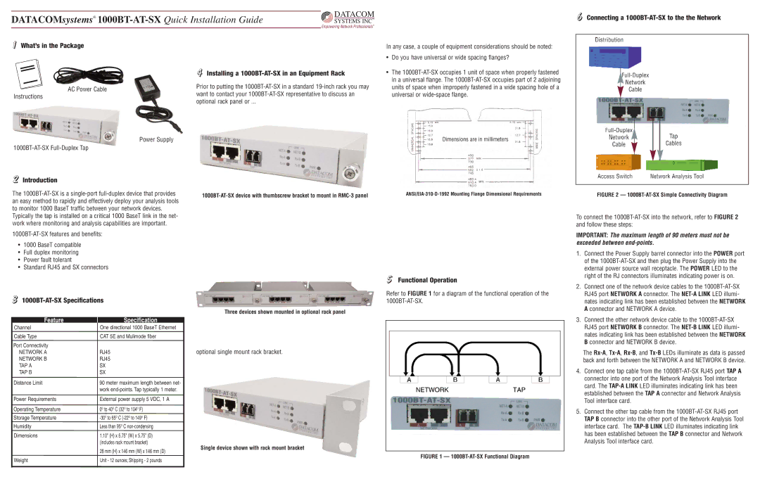
5 Functional Operation
FIGURE 2 — 1000BT-AT-SX Simple Connectivity Diagram
To connect the
IMPORTANT: The maximum length of 90 meters must not be exceeded between
1. | Connect the Power Supply barrel connector into the POWER port |
| of the |
| external power source wall receptacle. The POWER LED to the |
| right of the RJ connectors illuminates indicating power is on. |
2. | Connect one of the network device cables to the |
3 1000BT-AT-SX Specifications
Three devices shown mounted in optional rack panel
Refer to FIGURE 1 for a diagram of the functional operation of the
RJ45 port NETWORK A connector. The |
nates indicating link has been established between the NETWORK |
A connector and NETWORK A device. |
Feature
Channel
Cable Type
Port Connectivity
NETWORK A
NETWORK B
TAP A
TAP B
Distance Limit
Power Requirements
Operating Temperature
Storage Temperature Humidity
Dimensions
Weight
Specification
One directional 1000 BaseT Ethernet
CAT 5E and Mulimode fiber
RJ45
RJ45
SX
SX
90 meter maximum length between net- work
External power supply 5 VDC, 1 A
0O to 40O C (32O to 104O F)
1.10" (H) x 5.75" (W) x 5.75" (D) (includes rack mount bracket)
28 mm (H) x 146 mm (W) x 146 mm (D) Unit - 12 ounces; Shipping - 2 pounds
optional single mount rack bracket.
Single device shown with rack mount bracket
FIGURE 1 — 1000BT-AT-SX Functional Diagram
3. Connect the other network device cable to the |
RJ45 port NETWORK B connector. The |
nates indicating link has been established between the NETWORK |
B connector and NETWORK B device. |
The
4.Connect one tap cable from the
5.Connect the other tap cable from the