Mounting the Scanner
Cable Routing
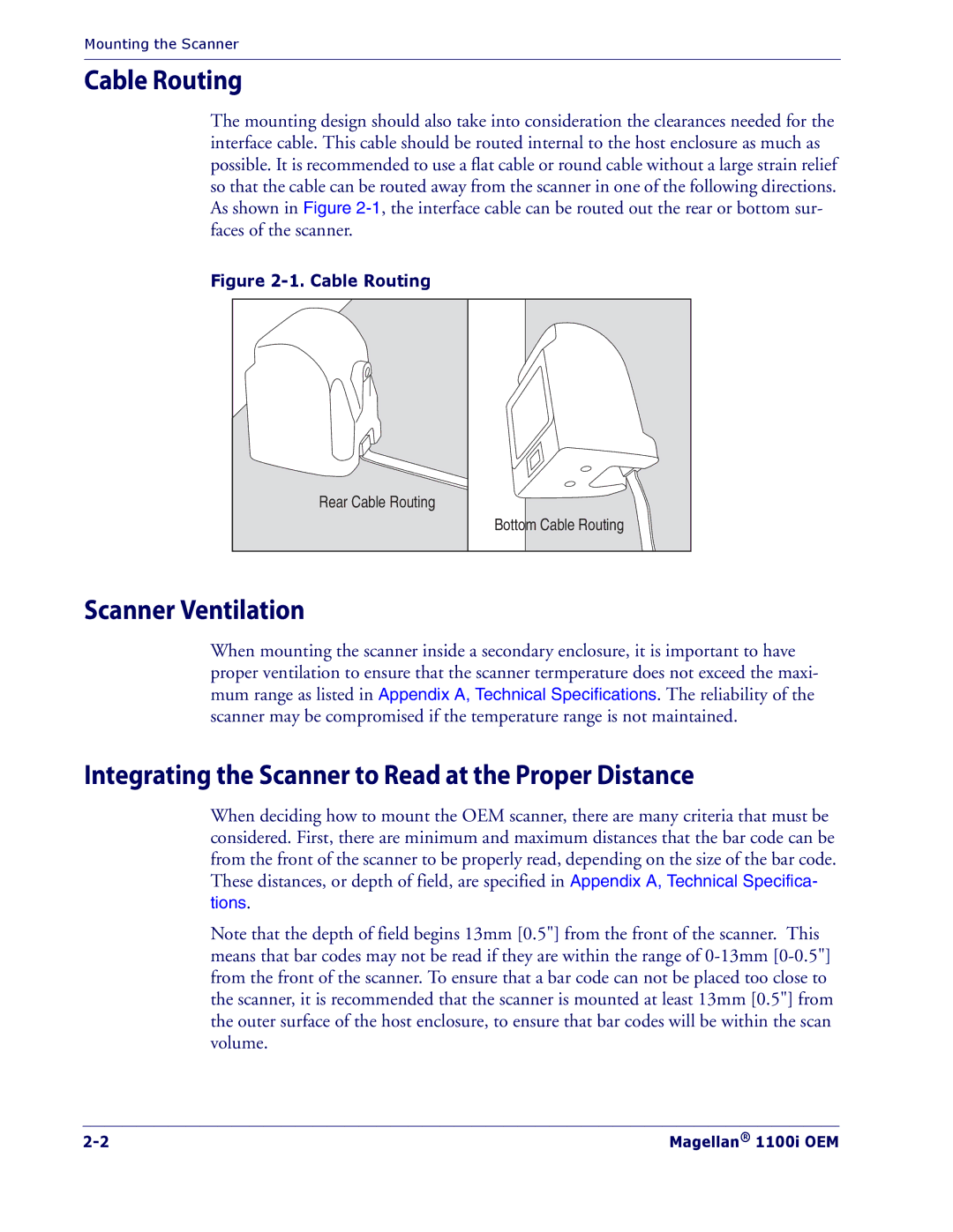
The mounting design should also take into consideration the clearances needed for the interface cable. This cable should be routed internal to the host enclosure as much as possible. It is recommended to use a flat cable or round cable without a large strain relief so that the cable can be routed away from the scanner in one of the following directions. As shown in Figure
Figure 2-1. Cable Routing
Rear Cable Routing
Bottom Cable Routing
Scanner Ventilation
When mounting the scanner inside a secondary enclosure, it is important to have proper ventilation to ensure that the scanner termperature does not exceed the maxi mum range as listed in Appendix A, Technical Specifications. The reliability of the scanner may be compromised if the temperature range is not maintained.
Integrating the Scanner to Read at the Proper Distance
When deciding how to mount the OEM scanner, there are many criteria that must be considered. First, there are minimum and maximum distances that the bar code can be from the front of the scanner to be properly read, depending on the size of the bar code. These distances, or depth of field, are specified in Appendix A, Technical Specifica tions.
Note that the depth of field begins 13mm [0.5"] from the front of the scanner. This means that bar codes may not be read if they are within the range of
Magellan® 1100i OEM |
