Quick Tour
1.
2.
3.
4.
5.
6.
7.
8.
9.
10.
11.
12.
13.
14.
15.
16.
17.
18.
19.
20.
21.
22.
23.
24.
25.
26.
27.
1
14
13
15
12![]()
![]()
11 ![]()
10
27
26![]()
25 ![]()
24
2
3
4
5
6
7
8
9
16
17
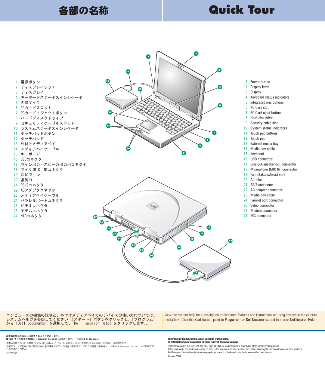
1.Power button
2.Display latch
3.Display
4.Keyboard status indicators
5.Integrated microphone
6.PC Card slot
7.PC Card eject button
8.
9.Security cable slot
10.System status indicators
11.Touch pad buttons
12.Touch pad
13.External media bay
14.Media bay cable
15.Keyboard
16.USB connector
17.
18.Microphone (MIC IN) connector
19.Fan intake/exhaust vent
20.Air inlet
21.PS/2 connector
22.AC adapter connector
23.Media bay cable
24.Parallel port connector
25.Video connector
26.Modem connector
27.NIC connector
23
22
21
20
18
19
13
© ![]()
![]()
![]()
View the system Help for a description of computer features and instructions on using devices in the external media bay. (Click the Start button, point to Programs> Dell Documents, and then click Dell Inspiron Help.)
Information in this document is subject to change without notice.
© 1999 Dell Computer Corporation. All rights reserved. Printed in Malaysia.
Trademarks used in this text: Dell, the DELL logo, BE DIRECT, and Inspiron are trademarks of Dell Computer Corporation.
Other trademarks and trade names may be used in this document to refer to either the entities claiming the marks and names or their products. Dell Computer Corporation disclaims any proprietary interest in trademarks and trade names other than its own.
October 1999