Dell
For information on removing and installing the system fans, see the Installing System Components chapter of the PowerEdge R210 II Owner’s Manual on Support.Dell.com for more information.
4.11 LED Control Panel
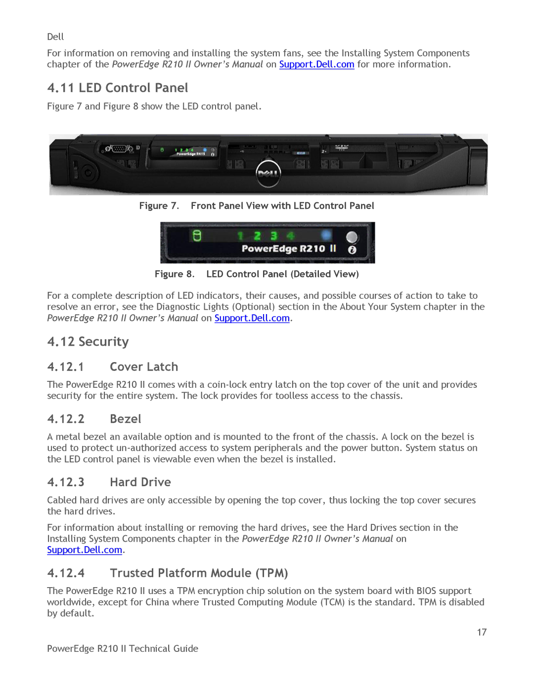
Figure 7 and Figure 8 show the LED control panel.
Figure 7. Front Panel View with LED Control Panel
Figure 8. LED Control Panel (Detailed View)
For a complete description of LED indicators, their causes, and possible courses of action to take to resolve an error, see the Diagnostic Lights (Optional) section in the About Your System chapter in the PowerEdge R210 II Owner’s Manual on Support.Dell.com.
4.12 Security
4.12.1Cover Latch
The PowerEdge R210 II comes with a
4.12.2Bezel
A metal bezel an available option and is mounted to the front of the chassis. A lock on the bezel is used to protect
4.12.3Hard Drive
Cabled hard drives are only accessible by opening the top cover, thus locking the top cover secures the hard drives.
For information about installing or removing the hard drives, see the Hard Drives section in the Installing System Components chapter in the PowerEdge R210 II Owner’s Manual on Support.Dell.com.
4.12.4Trusted Platform Module (TPM)
The PowerEdge R210 II uses a TPM encryption chip solution on the system board with BIOS support worldwide, except for China where Trusted Computing Module (TCM) is the standard. TPM is disabled by default.
17
PowerEdge R210 II Technical Guide