T3500 specifications
The Dell T3500 is a powerful workstation designed to meet the demanding needs of various professional environments, including engineering, design, and content creation. Launched as part of Dell’s Precision series, the T3500 stands out for its reliability, performance, and versatility.One of the hallmark features of the T3500 is its robust architecture. It is powered by Intel's Nehalem microarchitecture, supporting Intel Xeon processors that range from quad-core to six-core options. This allows users to select a configuration that meets their performance requirements, whether they are running complex simulations, rendering high-resolution graphics, or performing data analysis.
The T3500 supports up to 24GB of DDR3 ECC memory, which not only enhances performance but also ensures data integrity by correcting memory errors. This advanced memory configuration is crucial for professionals who rely on accuracy in their computations. Moreover, the workstation utilizes dual-channel memory architecture, further optimizing data throughput and overall system performance.
When it comes to graphics capabilities, the Dell T3500 offers several options, accommodating a range of professional graphics cards, including NVIDIA Quadro and ATI FirePro series. These high-performance graphics cards are designed to handle heavy graphical workloads, making the workstation ideal for 3D modeling, video editing, and CAD applications.
Storage flexibility is another important feature of the T3500. It offers multiple drive configurations, including traditional hard disk drives (HDD) and solid-state drives (SSD). Users can configure their systems with RAID options to ensure data redundancy and improve performance. The inclusion of a variety of connectivity options—such as USB 2.0, USB 3.0, and FireWire—adds further convenience for peripherals and external storage devices.
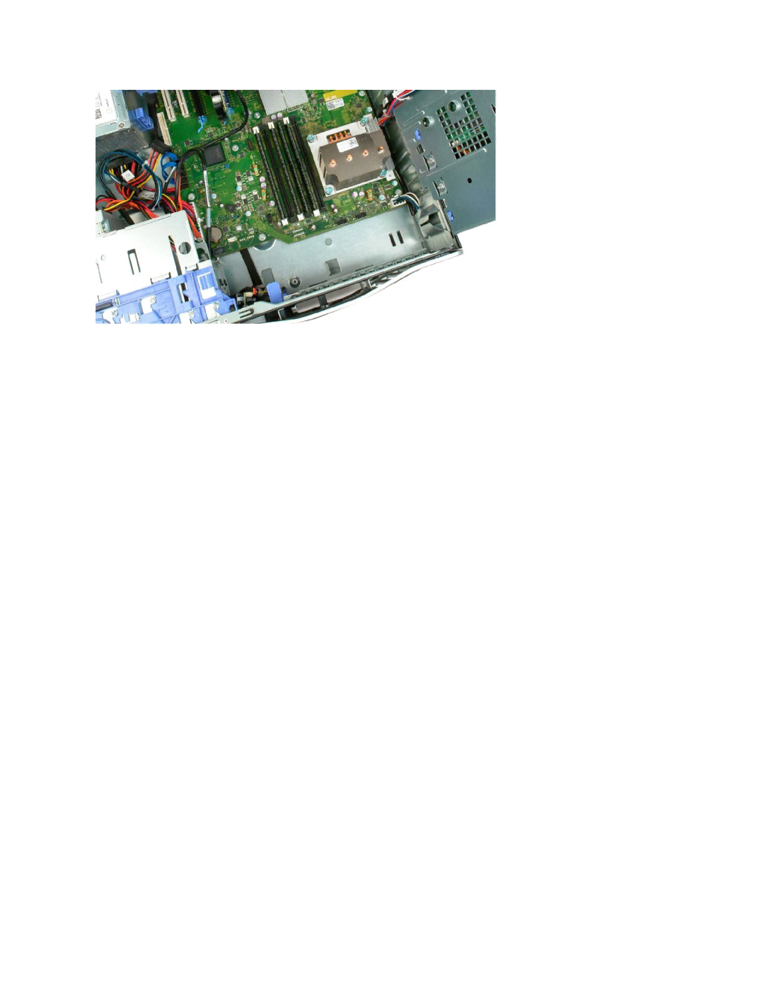
In terms of build quality, the Dell T3500 presents a professional aesthetic with a durable chassis designed to withstand the rigors of a busy workstation environment. Its efficient cooling system ensures that components remain at optimal temperatures, reducing the likelihood of thermal throttling and extending the overall lifespan of the system.
In conclusion, the Dell T3500 is a highly capable workstation that combines powerful performance features, robust technologies, and flexible configurations to serve the needs of professionals across various industries. Whether for scientific research, creative design, or computational tasks, the T3500 holds a strong position as a reliable choice in the realm of desktop workstations.