ADJUSTING HEIGHT OF RIGHT EDGE OF SLIDING TABLEL
A
B![]() C
C
C![]()
A![]()
B
![]() D
D
F
![]() K
K
G E
Fig. 49 | Fig. 50 | Fig. 51 |
H |
|
| J |
F |
|
G | E |
|
Fig. 52
M![]()
![]() L
L
Fig. 53
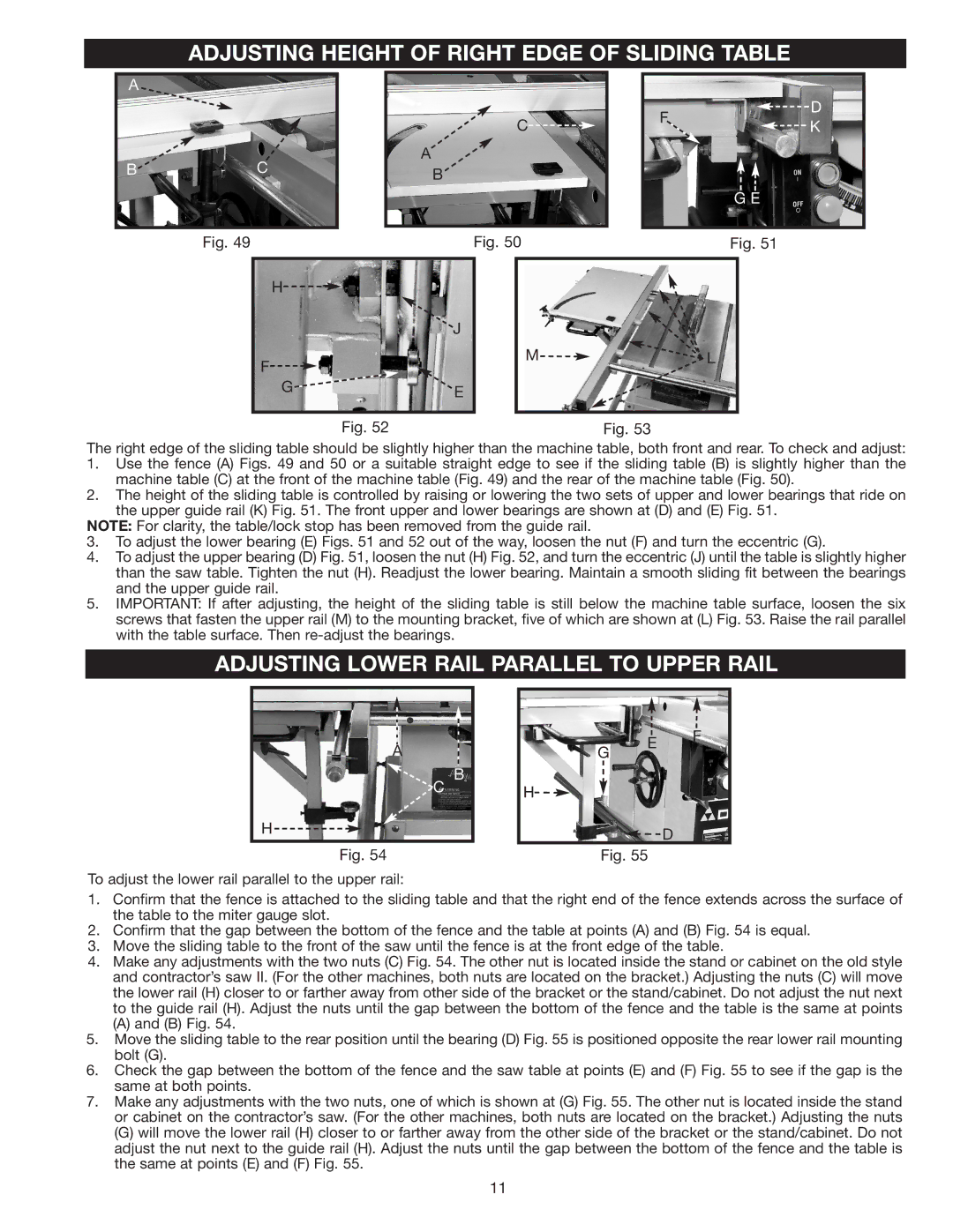
The right edge of the sliding table should be slightly higher than the machine table, both front and rear. To check and adjust:
1.Use the fence (A) Figs. 49 and 50 or a suitable straight edge to see if the sliding table (B) is slightly higher than the machine table (C) at the front of the machine table (Fig. 49) and the rear of the machine table (Fig. 50).
2.The height of the sliding table is controlled by raising or lowering the two sets of upper and lower bearings that ride on the upper guide rail (K) Fig. 51. The front upper and lower bearings are shown at (D) and (E) Fig. 51.
NOTE: For clarity, the table/lock stop has been removed from the guide rail.
3.To adjust the lower bearing (E) Figs. 51 and 52 out of the way, loosen the nut (F) and turn the eccentric (G).
4.To adjust the upper bearing (D) Fig. 51, loosen the nut (H) Fig. 52, and turn the eccentric (J) until the table is slightly higher than the saw table. Tighten the nut (H). Readjust the lower bearing. Maintain a smooth sliding fit between the bearings and the upper guide rail.
5.IMPORTANT: If after adjusting, the height of the sliding table is still below the machine table surface, loosen the six screws that fasten the upper rail (M) to the mounting bracket, five of which are shown at (L) Fig. 53. Raise the rail parallel with the table surface. Then
ADJUSTING LOWER RAIL PARALLEL TO UPPER RAIL
A
B
C
H
G
H![]()
E F
D
Fig. 54
Fig. 55
To adjust the lower rail parallel to the upper rail:
1.Confirm that the fence is attached to the sliding table and that the right end of the fence extends across the surface of the table to the miter gauge slot.
2.Confirm that the gap between the bottom of the fence and the table at points (A) and (B) Fig. 54 is equal.
3.Move the sliding table to the front of the saw until the fence is at the front edge of the table.
4.Make any adjustments with the two nuts (C) Fig. 54. The other nut is located inside the stand or cabinet on the old style and contractor’s saw II. (For the other machines, both nuts are located on the bracket.) Adjusting the nuts (C) will move the lower rail (H) closer to or farther away from other side of the bracket or the stand/cabinet. Do not adjust the nut next to the guide rail (H). Adjust the nuts until the gap between the bottom of the fence and the table is the same at points
(A)and (B) Fig. 54.
5.Move the sliding table to the rear position until the bearing (D) Fig. 55 is positioned opposite the rear lower rail mounting bolt (G).
6.Check the gap between the bottom of the fence and the saw table at points (E) and (F) Fig. 55 to see if the gap is the same at both points.
7.Make any adjustments with the two nuts, one of which is shown at (G) Fig. 55. The other nut is located inside the stand or cabinet on the contractor’s saw. (For the other machines, both nuts are located on the bracket.) Adjusting the nuts
(G)will move the lower rail (H) closer to or farther away from the other side of the bracket or the stand/cabinet. Do not adjust the nut next to the guide rail (H). Adjust the nuts until the gap between the bottom of the fence and the table is the same at points (E) and (F) Fig. 55.
11