ADJUSTING SLIDING TABLE PARALLEL WITH MACHINE TABLEL
Adjust the sliding table so that it is parallel with the machine table. (The sliding table must also be slightly higher than the machine table.) To check and adjust:
A ![]() C B
C B
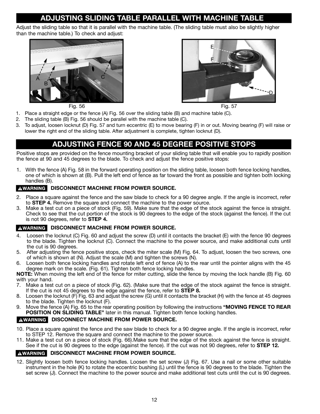
Fig. 56
E
F
![]() D
D
Fig. 57
1.Place a straight edge or the fence (A) Fig. 56 over the sliding table (B) and machine table (C).
2.The sliding table (B) Fig. 56 should be parallel with the machine table (C).
3.To adjust, loosen locknut (D) Fig. 57 and turn eccentric (E) to move bearing (F) in or out. Moving bearing (F) will raise or lower the right end of the sliding table. After adjustment is complete, tighten locknut (D).
ADJUSTING FENCE 90 AND 45 DEGREE POSITIVE STOPS
Positive stops are provided on the fence mounting bracket of your sliding table that will enable you to rapidly position the fence at 90 and 45 degrees to the blade. To check and adjust the fence positive stops:
1.With the fence (A) Fig. 58 in the forward operating position on the sliding table, loosen both fence locking handles, one of which is shown at (B). Pull the left end of fence as far toward the front as possible and tighten both locking handles (B).
DISCONNECT MACHINE FROM POWER SOURCE.
2.Place a square against the fence and the saw blade to check for a 90 degree angle. If the angle is incorrect, refer to STEP 4. Remove the square and connect the machine to the power source.
3.Make a test cut on a piece of stock (Fig. 59). Make sure that the edge of the stock against the fence is straight. Check to see that the cut portion of the stock is 90 degrees to the edge of the stock (against the fence). If the cut is not 90 degrees, refer to STEP 4.
DISCONNECT MACHINE FROM POWER SOURCE.
4.Loosen the locknut (C) Fig. 60 and adjust the screw (D) until it contacts the bracket (E) with the fence 90 degrees to the blade. Tighten the locknut (C). Connect the machine to the power source, and make additional cuts until the cut is 90 degrees.
5.After adjusting the fence positive stops, check the miter scale (M) Fig. 64. To adjust, loosen the two screws, one of which is shown at (N). Adjust the scale (M) and tighten the screws (N).
6.Loosen both fence locking handles and rotate left end of fence (A) to the rear until the pointer aligns with the 45 degree mark on the scale. (Fig. 61). Tighten both fence locking handles.
NOTE: When moving the left end of the fence for miter cutting, slide the fence by moving the lock handle (B) Fig. 60 with your hand.
7.Make a test cut on a piece of stock (Fig. 62). (Make sure that the edge of the stock against the fence is straight. If the cut is not 45 degrees to the edge against the fence, refer to STEP 8.
8.Loosen the locknut (F) Fig. 63 and adjust the screw (G) until it contacts the bracket (H) with the fence at 45 degrees to the blade. Tighten the locknut (F).
9.Move the fence (A) Fig. 65 to the rear operating position by following the instructions “MOVING FENCE TO REAR POSITION ON SLIDING TABLE” later in this manual. Tighten both fence locking handles.
DISCONNECT MACHINE FROM POWER SOURCE.
10.Place a square against the fence and the saw blade to check for a 90 degree angle. If the angle is incorrect, refer to STEP 12. Remove the square and connect the machine to the power source.
11.Make a test cut on a piece of stock (Fig. 66).Make sure that the edge of the stock against the fence is straight. See if the cut is 90 degrees to the edge (against the fence). If the cut was not 90 degrees, refer to STEP 12.
DISCONNECT MACHINE FROM POWER SOURCE.
12.Slightly loosen both fence locking handles. Loosen the set screw (J) Fig. 67. Use a nail or some other suitable instrument in the hole (K) to rotate the eccentric bushing (L) until the fence is 90 degrees to the blade. Tighten the set screw (J). Connect the machine to the power source and make additional test cuts until the cut is 90 degrees.
12