ASSEMBLY
![]() FOR YOUR OWN SAFETY, DO NOT CONNECT THE MACHINE TO THE POWER SOURCE UNTIL THE MACHINE IS COMPLETELY ASSEMBLED AND YOU READ AND UNDERSTAND THE ENTIRE INSTRUCTION MANUAL.
FOR YOUR OWN SAFETY, DO NOT CONNECT THE MACHINE TO THE POWER SOURCE UNTIL THE MACHINE IS COMPLETELY ASSEMBLED AND YOU READ AND UNDERSTAND THE ENTIRE INSTRUCTION MANUAL.
RAISING AND LOWERING HANDLE
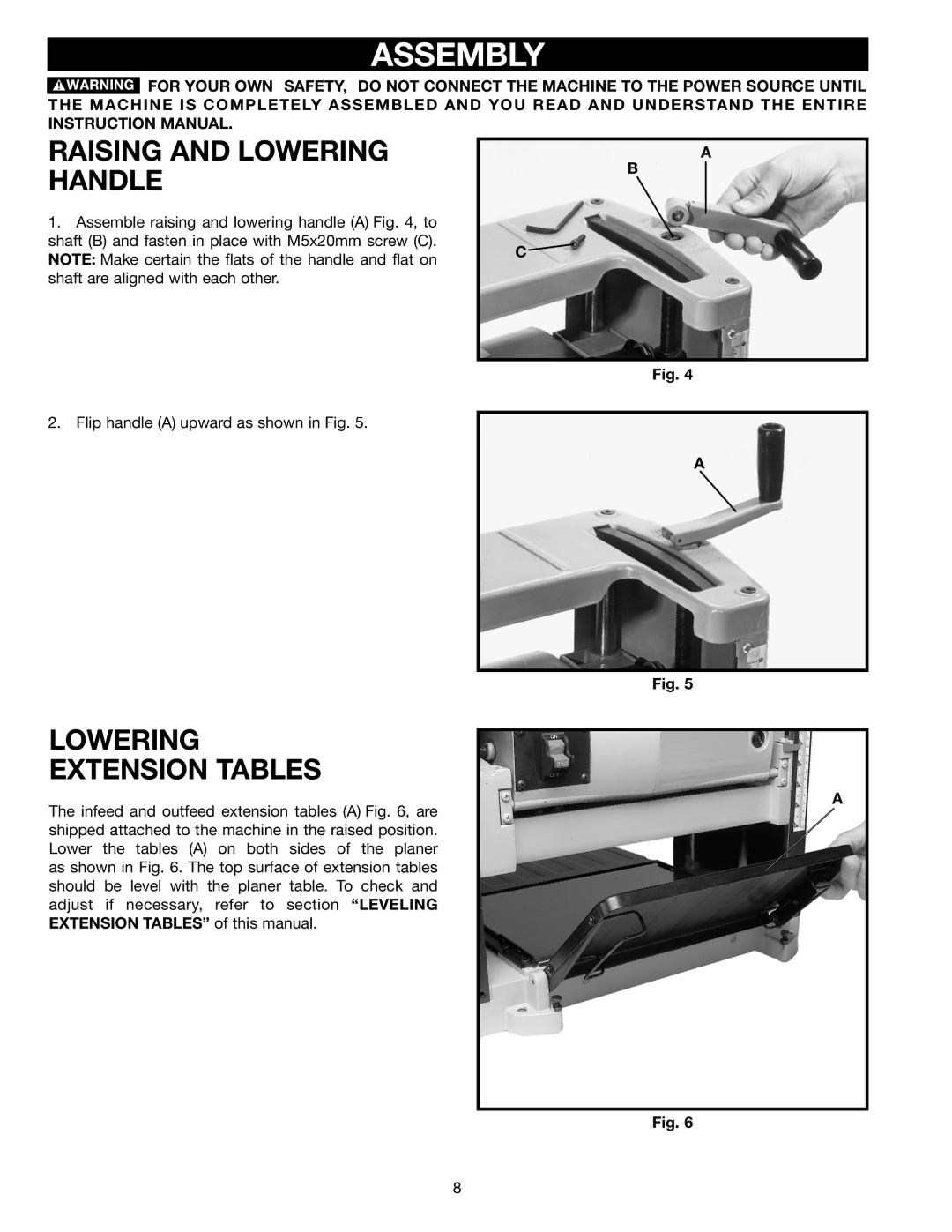
1.Assemble raising and lowering handle (A) Fig. 4, to shaft (B) and fasten in place with M5x20mm screw (C). NOTE: Make certain the flats of the handle and flat on shaft are aligned with each other.
A
B
C ![]()
Fig. 4
2. Flip handle (A) upward as shown in Fig. 5.
A
Fig. 5
LOWERING
EXTENSION TABLES
The infeed and outfeed extension tables (A) Fig. 6, are shipped attached to the machine in the raised position. Lower the tables (A) on both sides of the planer as shown in Fig. 6. The top surface of extension tables should be level with the planer table. To check and adjust if necessary, refer to section “LEVELING EXTENSION TABLES” of this manual.
A
Fig. 6
8