For
R1 = | [(Voset ,PS 2 | + ∆V ) − Vref ] | * 20K Ω | (1) | |
| Vref |
| |||
|
|
|
| ||
Note:
1.Vref =0.4×Voset,PS2 , please refer to Table 5 for Vref set value.
2.△V is the maximum difference of voltage between PS1 and PS2 supply voltage.
For example, the PS1 Voset,PS1=5V, the PS2 Voset,PS2=3.3V, R1 is calculated as follows:
R1 = | [(3.3 + 1.7) − 1.32] | * 20K = 55.75K Ω | |
1.32 |
| ||
|
|
| |
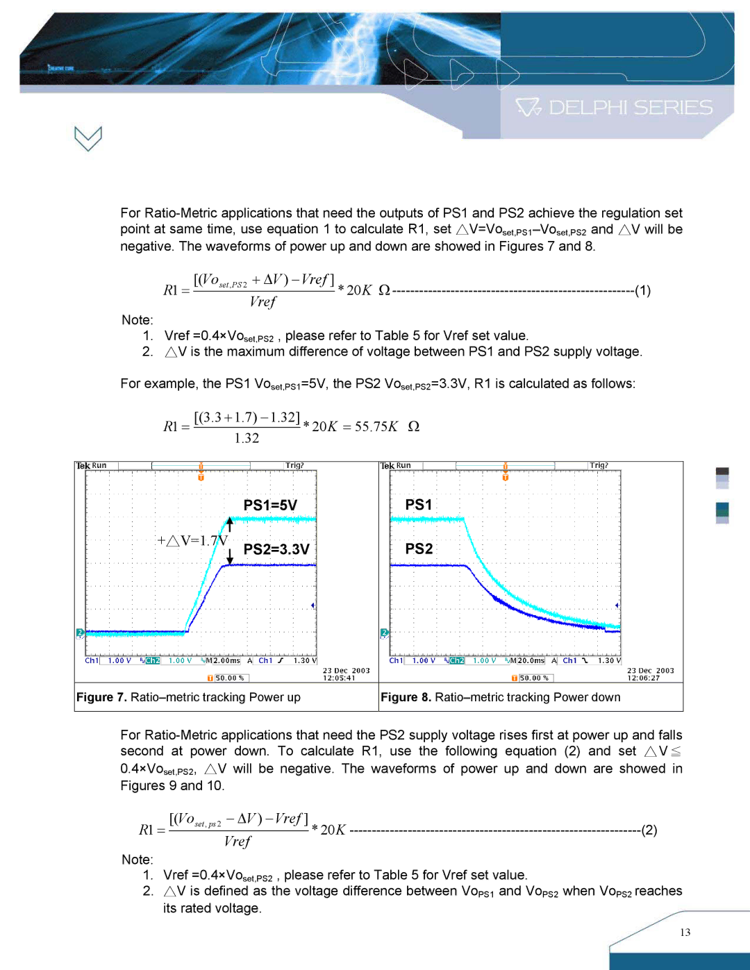
PS1=5V
+△V=1.7V PS2=3.3V
PS1
PS2
Figure 7. Ratio–metric tracking Power up
Figure 8. Ratio–metric tracking Power down
For
0.4×Voset,PS2, △V will be negative. The waveforms of power up and down are showed in Figures 9 and 10.
R1 = | [(Voset , ps 2 | − ∆V ) − Vref ] | * 20K | (2) |
| Vref | |||
|
|
|
|
Note:
1.Vref =0.4×Voset,PS2 , please refer to Table 5 for Vref set value.
2.△V is defined as the voltage difference between VoPS1 and VoPS2 when VoPS2 reaches its rated voltage.
13