TEST CONFIGURATIONS
| TO OSCILLOSCOPE | |
| L | VI(+) |
|
| |
BATTERY | 2 | 100uF |
| Tantalum | |
|
| |
Note: Input
Figure 23: Input reflected-ripple test setup
COPPER STRIP
Vo
| 10uF |
| 1uF | SCOPE | Resistive |
|
|
| |||
tantalum | ceramic | Load | |||
GND
Note: Use a 10µF tantalum and 1µF capacitor. Scope measurement should be made using a BNC connector.
Figure 24: Peak-peak output noise and startup transient measurement test setup.
|
|
|
|
|
| CONTACT AND | ||
|
|
|
|
|
| DISTRIBUTION LOSSES | ||
|
|
| VI | Vo |
| |||
|
|
|
|
|
|
| ||
|
|
|
|
|
|
| ||
|
|
|
|
|
|
|
| |
| II |
|
|
|
|
| Io |
|
SUPPLY |
|
|
|
|
| LOAD | ||
|
|
| GND |
|
|
| ||
|
|
|
|
|
|
|
|
|
CONTACT RESISTANCE
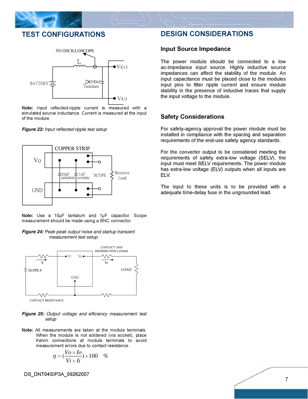
Figure 25: Output voltage and efficiency measurement test setup
Note: All measurements are taken at the module terminals. When the module is not soldered (via socket), place Kelvin connections at module terminals to avoid measurement errors due to contact resistance.
η = (Vo × Io) ×100 %
Vi × Ii
DS_DNT04SIP3A_09262007
DESIGN CONSIDERATIONS
Input Source Impedance
The power module should be connected to a low
Safety Considerations
For
For the converter output to be considered meeting the requirements of safety
The input to these units is to be provided with a adequate
7