FEATURES DESCRIPTIONS
Remote On/Off
The DNT series power modules have an On/Off pin for remote On/Off operation. Both positive and negative On/Off logic options are available in the DNT series power modules.
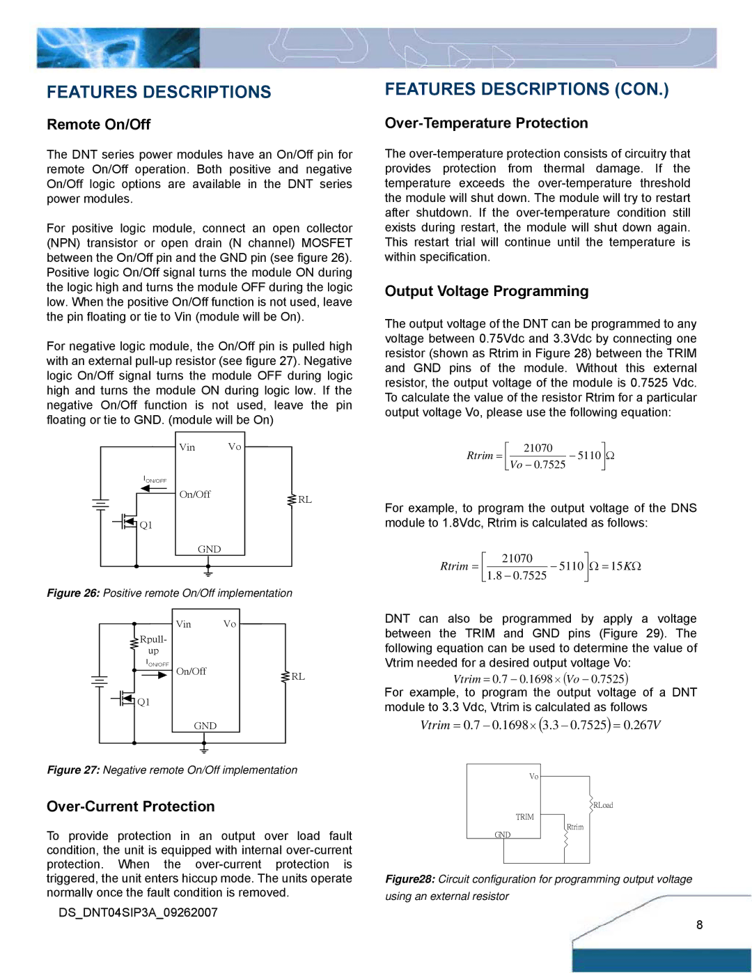
For positive logic module, connect an open collector (NPN) transistor or open drain (N channel) MOSFET between the On/Off pin and the GND pin (see figure 26). Positive logic On/Off signal turns the module ON during the logic high and turns the module OFF during the logic low. When the positive On/Off function is not used, leave the pin floating or tie to Vin (module will be On).
For negative logic module, the On/Off pin is pulled high with an external
Vin Vo
ION/OFF
On/OffRL
![]() Q1
Q1
GND
Figure 26: Positive remote On/Off implementation
Vin Vo
Rpull-
up
ION/OFF
On/OffRL
![]() Q1
Q1
GND
Figure 27: Negative remote On/Off implementation
Over-Current Protection
To provide protection in an output over load fault condition, the unit is equipped with internal
DS_DNT04SIP3A_09262007
FEATURES DESCRIPTIONS (CON.)
Over-Temperature Protection
The
Output Voltage Programming
The output voltage of the DNT can be programmed to any voltage between 0.75Vdc and 3.3Vdc by connecting one resistor (shown as Rtrim in Figure 28) between the TRIM and GND pins of the module. Without this external resistor, the output voltage of the module is 0.7525 Vdc. To calculate the value of the resistor Rtrim for a particular output voltage Vo, please use the following equation:
⎡ | 21070 | ⎤ |
Rtrim = ⎢ |
| − 5110⎥Ω |
| ||
⎣Vo − 0.7525 | ⎦ | |
For example, to program the output voltage of the DNS module to 1.8Vdc, Rtrim is calculated as follows:
⎡ | 21070 | ⎤ | |
Rtrim = ⎢ |
|
| − 5110⎥Ω = 15KΩ |
| − 0.7525 | ||
⎣1.8 | ⎦ | ||
DNT can also be programmed by apply a voltage between the TRIM and GND pins (Figure 29). The following equation can be used to determine the value of Vtrim needed for a desired output voltage Vo:
Vtrim = 0.7 − 0.1698× (Vo − 0.7525)
For example, to program the output voltage of a DNT module to 3.3 Vdc, Vtrim is calculated as follows
Vtrim = 0.7 − 0.1698× (3.3 − 0.7525) = 0.267V
Vo
RLoad
TRIM
Rtrim
GND
Figure28: Circuit configuration for programming output voltage using an external resistor
8