Parameter | | | | and | | | | : | | | | can be set up when parameter | | | | | is set as “0”. | |
| | | | | | | | | is not “0”. | | | | | | | | | | | | | | | | | | |
can be set up when | | | | | | | | | | | | | | | | | | | | | | |
| | | | | | | | | | | | | | | | | | | | | |
Parameter | | | | and | | | | : | | | | (control cycle for output 1) can be set up when parameter |
| is set as | | | | | (heating) or | | | | (cooling) output. | | | | (control cycle for output 2) |
| | | | | | | | | | |
| | | | is set as | | (heating) or | | | | | | (cooling) output. |
can be set up when parameter | | | | | | | | |
| | | | | | | |
Parameter | | | and | | | | :Can be set up when parameter | | | | and | | | | are set as |
| (heating) or | | | | | | (cooling) output. (The settings in | | and | | | | have to be |
| | | | | | | | | |
different.) | | | | | | | | | | | | | | | | | | | | | | | | | | | | |
For ON/OFF Control Application:
1.Set up 2 outputs: Enter parameter  and
and  in “initial setting mode” (see “Setting up
Parameters” section for details). Set up one of the two parameters as  or
or  of control output.
2.Set up control type: Enter parameter  in “initial setting mode” (see “Setting up Parameters”
section for details) and set it up as  (ON/OFF) control.
3.Set up parameters: In “regulation mode”
Parameters  and
and  :
: (hysteresis for output 1) can be set up when parameter
  is set as
  (heating)
  (cooling) output.
  (hysteresis for output 2) can be
set up when parameter  is set as
  (heating) or
  (cooling) output. You can
only set up  when
when  and
and  are set as
  or
or  at the same time.
Parameter  :Can be set up when parameter
  and
and  are set as control output,
and the settings in  and
and  are different, e.g. output 1 is
  (heating), and output
2 is  (cooling).
For Manual Control Application:
1.Set up 2 outputs: Enter parameter  and
and  in “initial setting mode” (see “Setting up
Parameters” section for details). Set up one of the two parameters as  or
or  of control output.
2.Set up control type: Enter parameter  in “initial setting mode” (see “Setting up Parameters”
section for details) and set it up as  (manual) control.
3.Set up parameters: In “regulation mode”
Parameter  and
and  :
: (control cycle for output 1) can be set up when parameter
  is set as
  (heating) or
  (cooling) output.
  (control cycle for output 2)
can be set up when parameter  is set as
  (heating) or
  (cooling) output.
Parameter  and
and  (in “operation mode”):
 can be set up when parameter
 is set as
  (heating) or
  (cooling) output.
  can be set up when
parameter  is set as
  (heating) or
  (cooling) output.
For Programmable PID Application:
1.Set up 2 outputs: Enter parameter  and
and  in “initial setting mode” (see “Setting up
Parameters” section for details). Set up one of the two parameters as  or
or  of control output.
2.Set up control type: Enter parameter  in “initial setting mode” (see “Setting up Parameters”
section for details) and set it up as  (programmable) control.
3.Set up parameters: In “regulation mode”
Parameter  ,
,  and
and  .
.
Parameter  :
: can be set up when parameter
  is set as “0”.
Parameter  and
and  :
: (control cycle for output 1) can be set up when parameter
 is set as
  (heating) or
  (cooling) output.
  (control cycle for output 2)
can be set up when parameter  is set as
  (heating) or
  (cooling) output.
Parameter  and
and  :Can be set up when parameter
  and
and  are set as
  (heating) or
  (cooling) output. (The settings in
  and
and  have to be different.)
Parameter  and
and  (in “operation mode"):Can be set up when parameter
  is
is
set as  or
or  .
.
For Proportional Output Application: In this application, output 1 has to be analog output.
1.Set up output function: Enter parameter  in “initial setting mode” (see “Setting up Parameters”
section for details) and set it as  (proportional) output.
2.Set up parameters: In “regulation mode”
Parameter 
For Upper/Lower Limits of Control Output:
1.Set up upper limit: Enter parameter  in “regulation mode” (see “Setting up Parameters”
section for details). Range: Lower limit ~ 100%.
2.Set up lower limit: Enter parameter  in “regulation mode” (see “Setting up Parameters”
section for details). Range: 0 ~ upper limit %.
For Alarm Application:
1. Set up output function (only when there is group INB): Enter parameter  in “initial setting
mode” (see “Setting up Parameters” section for details) and set it as  (alarm) output.
2.Set up alarm type: Enter parameter  (with INB) or
  and
and  (without INB) in “initial setting mode”. See Table 2 for more details on the alarm output.
3.Set up parameters: In “operation mode”
Parameter  and
and  :Can be set up when there is group INB.
Parameter  ,
,  ,
,  and
and  :Can be set up when there is no group INB.
4.Set up delay alarm output: Enter parameter  in “regulation mode” (unit: second). The alarm will be enabled only when the temperature reaches the alarm output condition, and the condition remains until the delay time is reached.
DTE main unit offers 2 groups of alarm output, each with 12 alarm modes in the initial setting mode. When SV is higher or lower than SV, the alarm output will be enabled. See the table in the next column for the explanations on the 12 alarm output modes.
Note: AL-H and AL-L include AL1H, AL2H and AL1L, AL2L.
| SV | | Alarm Mode | | Alarm Output Operation |
0 | | No alarm | | | | | | | | | | | | | | | | | | | | | | | | | | | | | OFF | | | | |
| | | Alarm output is enabled when the temperature reaches upper | | ON | | | | | | | | | | | | | | | | | | | | |
| | | | | | | | | | | | | | | | | | |
1 | | and lower limits: The alarm will be enabled when PV exceeds | | OFF | | | | | | | | | | | | | | | | | | | | | | | |
| | | | | | | | | | | | | | | | | | | | | | | | |
| | | SV + AL-H or falls below SV – A L-L. | | | | | | | | | | | | | | | | | | | | AL-L | SV | AL-H |
| | | Alarm output will be enabled when the temperature reaches the | | ON | | | | | | |
| | | | | | | | | |
2 | | upper limit: The alarm will be enabled when PV exceeds SV + | | OFF | | | | | | | | | | | | | | | | | | | | | | | | | | | | | | |
| | | | | | | | | | | | | | | | | | | | | | | | | | | | | | | |
| | | AL-H. | | | | | | | | | | | | | | | | | | | | | | | | | | | | | | SV | AL-H |
| | | Alarm output will be enabled when the temperature reaches the | | ON | | | | | | | | | | | | | | | | | | | | | | | |
| | | | | | | | | | | | | | | | | | | |
3 | | lower limit: The alarm will be enabled when PV falls below SV – | | OFF | | | | | | | | | | | | | | | | | | | | | | | |
| | | | | | | | | | | | | | | | | | | | | | | | |
| | | A L-L. | | | | | | | | | | | | | | | | | | | | AL-L | SV | | | | |
4 | | Alarm output will be enabled when PV is between SV + AL-H | | ON | | | | | | | |
| | | | | | | | |
| | OFF | | | | | | | | | | | | | | | | | | |
| and SV – AL-L. | | | | AL-L | SV | AL-H |
| | | | | | | | | | | | | | | | | | | | | |
| | | | | | | | | | | | | | | | | | | | | | | | | | | | |
| | | Alarm output will be enabled when the temperature reaches the | | ON | | | | | | | | | | | | | | | | | | |
| | | | | | | | | | | | | | | |
5 | | absolute value of the upper and lower limits: The alarm will be | | OFF | | | | | | | | | | | | | | | | | | | |
| | | | | | | | | | | | | | | | | | | | |
| | | enabled when PV exceeds AL-H or falls below AL-L. | | | | | | | | | | | | | | | | | | | | AL-L | | | AL-H |
| | | Alarm output will be enabled when the temperature reaches the | | ON | | | | | | |
| | | | | | | | | |
6 | | absolute value of the upper limit: The alarm will be enabled | | OFF | | | | | | | | | | | | | | | | | |
| | | | | | | | | | | | | | | | | | |
| | | when PV exceeds AL-H. | | | | | | | | | | | | | | | | | | | | | | | | | | | | | | | | AL-H |
| | | Alarm output will be enabled when the temperature reaches the | | ON | | | | | | | | | | | | | | | | | | |
| | | | | | | | | | | | | | |
7 | | absolute value of the lower limit: The alarm will be enabled when | | OFF | | | | | | | | | | | | | | | |
| | | | | | | | | | | | | | | | |
| | | PV falls below AL-L. | | | | | | | | | | | | | | | | | | | | AL-L | | | | | | |
| | | Upper/lower limit standby alarm: The alarm will be enabled when | | ON | | | | | | | | | | | | | | | | | | | | | | | | |
| | | | | | | | | | | | | |
8 | | PV reaches SV and further exceeds SV + AL-H or falls below | | OFF | | | | | | | | | | | | | | | | |
| | | | | | | | | | | | | | | | | |
| | | SV – AL –L. | | | | | | | | | | | | | | | | | | | | AL-L | SV | AL-H |
9 | | Upper limit standby alarm: The alarm will be enabled when PV | | ON | | | | | | |
| | | | | | | |
| | OFF | | | | | | | | | | | | | | | | | | | | | | | | | |
| reaches SV and further exceeds SV + AL-H. | | | | | | | | SV | AL-H |
| | | | | | | | | | | | | | | | | | | | | | | | | | | | | | | |
| | | | | | | | | | | | | | | | | | | | | | | | | | | | | | | | |
| | | | | | | | | | | | | | | | | |
10 | | Lower limit standby alarm: The alarm will be enabled when PV | | ON | | | | | | | | | | | | | | | | | | | | | | | | | |
| | | | | | | | | | |
| | OFF | | | | | | | | | | | | | | | | | | | | | | | | | | | | | | | | |
| reaches SV and further falls below SV – AL-L. | | | | | AL-L | SV | | | | |
| | | | | | | | | | | | | | | | | | | | | | | | | |
| | | | | | | | | | | | | | | | | | | | | | | | | | |
| | | | | | | | | | | | | | |
| | | Upper limit hysteresis alarm: The alarm will be enabled when PV | | ON | | | | | | |
| | | | | | | | | |
11 | | exceeds SV + AL-H. The alarm will be disabled when PV falls | | OFF | | | | | | | | | |
| | | | | | | | | | |
| | | below SV. | | | | | | | | | | | | | | | | | | | | AL-L | SV | AL-H |
| | | Lower limit hysteresis alarm: The alarm will be enabled when PV | | ON | | | | | | | | | | | | | | | | | |
| | | | | | | | | | | |
| 12 | falls below SV – AL-L. The alarm will be disabled when PV | | OFF | | | | | | | | | |
| | | | | | | | | | |
| | | exceeds SV. | | | | | | | | | | | | | | | | | | | | AL-L | SV | | AL-H |
Table 2
Setting up Communication
1.Set up communication: Enter parameter  ,
,  ,
,  ,
,  ,
,  and
and  in “initial setting mode” (see “Setting up Parameters” section for details) and select your desired communication settings.
2.DTE series temperature controller is able to set up or read communication settings through DTE-2DS.
Selecting Channel
1.Select channel: Enter parameter  in “regulation mode” (see “Setting up Parameters” section for details) and select the channel to be monitored.
2.How does it work: DTE main unit has maximum 8 channels which can be connected to 8 input sensors at the same time. The 8 input channels belong to group INA and INB, each group with 4 input channels. INB is optional accessory; therefore if INB is not inserted in DTE, DTE will only show 4 channels.
Setting up Copy Function
1. Set up the function: Enter parameter  in “initial setting mode” (see “Setting up Parameters”
section for details) and select the function you desire.
2.How does it work: The copy function allows a DTE main unit to copy its parameters (including the values set in the parameter and communication settings) to another DTE main unit through DTE-2DS. Follow the steps below:
a.Insert DTE-2DS into the DTE main unit to be copied. Enter parameter  in “initial setting
mode” and select  , and DTE-2DS will read the parameters in the DTE main unit. Next, you
will see  on the screen, indicating that the copy is successful.
  indicates the copy
fails. Press  to return to “operation mode” and you will see the present temperature value (PV) and set temperature value (SV).
b.Switch off DTE and withdraw DTE-2DS. Insert DTE-2DS into another DTE main unit. Enter
parameter  in “initial setting mode” and select
  . DTE-2DS will write the
parameters into it. Next, you will see  on the screen, indicating that the writing-in is
successful.  indicates the writing-in fails. Press
  to return to “operation mode” and you will see the present temperature value (PV) and set temperature value (SV).
Locking the Keys on Panel
1.Lock the keys: Enter parameter  in “operation mode” (see “Setting up Parameters” section for details) and select the function you desire.
2.How does it work:  indicates locking all the keys on the panel.
  indicates that you can only modify the set temperature value (SV), and all other functions are locked.
3.Press  and
and  at the same time to unlock the keys.
Analog Output & Temperature Tuning
1.Set up analog output tuning: Enter parameter  and
and  in “regulation mode” (see “Setting up Parameters” section for details) and tune the parameter to the desired output value.
2.Temperature offset tuning: Enter parameter  in “regulation mode” and tune the parameter to the displayed temperature value.
3.How does it work:
a.Tuning analog output: For example, if you would like to have accurate 4 ~ 20mA of output, you can set up output 0% by manual control, connect the output to ampere meter and tune
parameter  making the meter point to 4mA. Next, set up output 100% by manual control
and tune parameter  making the meter point to 20mA.
b.Tuning temperature offset: This allows the displayed temperature to plus or minus 1 offset value.
Error Message
Error | | PV | | | SV |
Input sensor not connected | | | | | | | |
| | | | | | | |
Internal communication error | | | | | | | |
| | | | | | |
| | | | | | | |
Output error | | | | | | | |
| | | | | | |
| | | | | | | |
Input error | | | | | | | |
| | | | | | |
| | | | | | | |
Storage error | | | | | | | |
| | | | | | |
| | | | | | | |
Channel disabled | | | | | | | |
| | | | | | |
| | | | | | | |
Channel being initialized | | | | | | | |
| | | | | | |
| | | | | | | |
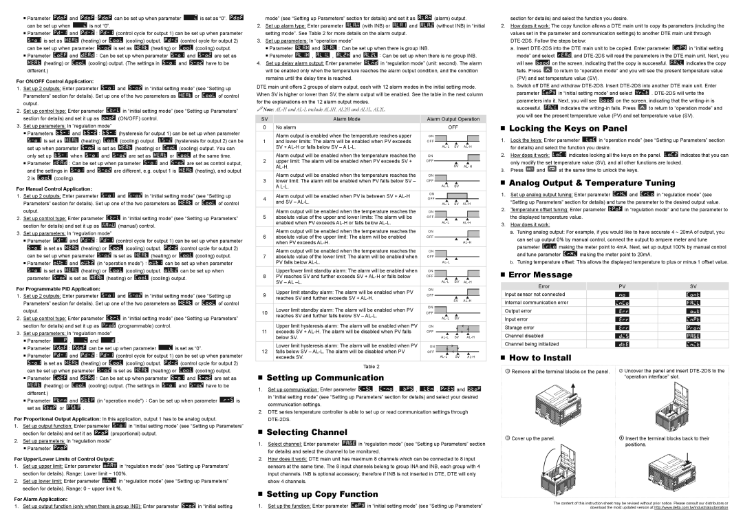
How to Install
1 Remove all the terminal blocks on the panel. 2 Uncover the panel and insert DTE-2DS to the “operation interface” slot.
3 Cover up the panel. | 4 Insert the terminal blocks back to their |
| positions. |
The content of this instruction sheet may be revised without prior notice. Please consult our distributors or download the most updated version at http://www.delta.com.tw/industrialautomation