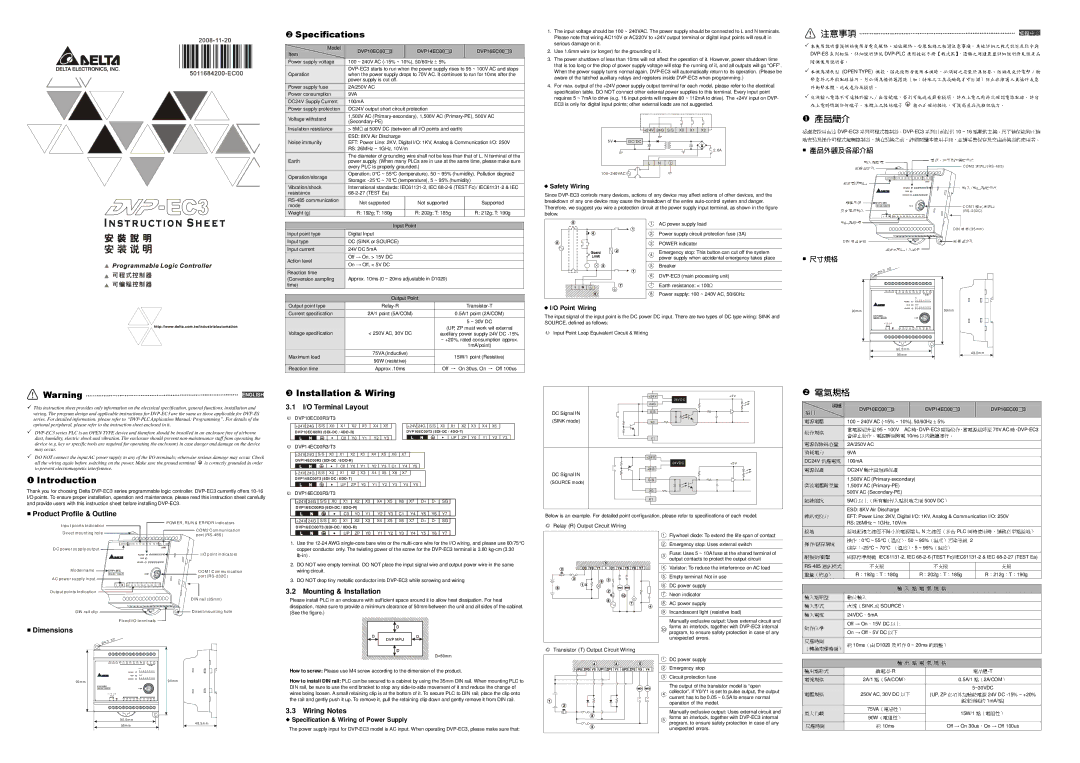
Warning
This instruction sheet provides only information on the electrical specification, general functions, installation and wiring. The program design and applicable instructions for
DO NOT connect the input AC power supply to any of the I/O terminals; otherwise serious damage may occur. Check
all the wiring again before switching on the power. Make sure the ground terminal is correctly grounded in order to prevent electromagnetic interference.
Introduction
Thank you for choosing Delta
Specifications
Model | DVP10EC00 | 3 | DVP14EC00 | 3 | DVP16EC00 | 3 | |
Item | |||||||
|
|
|
|
|
| ||
Power supply voltage | 100 ~ 240V AC |
|
|
| |||
| |||||||
Operation | when the power supply drops to 70V AC. It continues to run for 10ms after the | ||||||
| power supply is cut off. |
|
|
|
| ||
Power supply fuse | 2A/250V AC |
|
|
|
|
| |
Power consumption | 9VA |
|
|
|
|
| |
DC24V Supply Current | 100mA |
|
|
|
|
| |
Power supply protection | DC24V output short circuit protection |
|
|
| |||
Voltage withstand | 1,500V AC |
| |||||
|
|
|
|
| |||
|
|
|
|
|
| ||
Insulation resistance | > 5M at 500V DC (between all I/O points and earth) |
|
| ||||
| ESD: 8KV Air Discharge |
|
|
|
| ||
Noise immunity | EFT: Power Line: 2KV, Digital I/O: 1KV, Analog & Communication I/O: 250V | ||||||
| RS: 26MHz ~ 1GHz, 10V/m |
|
|
|
| ||
| The diameter of grounding wire shall not be less than that of L, N terminal of the | ||||||
Earth | power supply. (When many PLCs are in use at the same time, please make sure | ||||||
| every PLC is properly grounded.) |
|
|
| |||
Operation/storage | Operation: 0°C ~ 55°C (temperature), 50 ~ 95% (humidity), Pollution degree2 | ||||||
Storage: |
|
| |||||
|
|
| |||||
Vibration/shock | International standards: | ||||||
resistance |
|
|
|
|
| ||
Not supported□ |
| Not supported□ |
| Supported | □ | ||
mode |
|
| |||||
Weight (g) | R: 192g; T: 180g | R: 202g; T: 185g | R: 212g; T: 190g |
Input Point
Input point type | Digital Input |
Input type | DC (SINK or SOURCE) |
Input current | 24V DC 5mA |
Off → On, > 15V DC
Action level
| On → Off, < 5V DC |
Reaction time |
|
(Conversion sampling | Approx. 10ms (0 ~ 20ms adjustable in D1020) |
time) |
|
Output Point
Output point type |
|
| ||
Current specification | 2A/1 point (5A/COM) |
| 0.5A/1 point (2A/COM) | |
|
|
| 5 ~ 30V DC |
|
Voltage specification | < 250V AC, 30V DC | (UP, ZP must work wit external | ||
auxiliary power supply 24V DC | ||||
|
| ~ +20%, rated consumption approx. | ||
|
|
| 1mA/point) |
|
Maximum load | 75VA (inductive) |
| 15W/1 point (Resistive) | |
90W (resistive) |
| |||
|
|
|
| |
Reaction time | Approx .10ms | Off | On 30us, On | Off 100us |
Installation & Wiring |
|
|
|
|
|
|
|
|
|
|
| ||||||||
3.1 | I/O Terminal Layout |
|
|
|
|
|
|
|
|
|
|
|
|
|
| ||||
DVP10EC00R3/T3 |
|
|
|
|
|
|
|
|
|
|
|
|
|
|
|
|
| ||
+24V 24G S/S | X0 | X1 | X2 | X3 | X4 | X5 | +24V 24G | S/S | X0 | X1 | X2 | X3 | X4 | X5 |
| ||||
D VP 10 EC 00 R3 (6 DI |
|
|
|
| DVP10EC00 T3 (6DI- DC / 4DO- T) |
|
|
|
| ||||||||||
|
|
| C0 | Y0 | Y1 | Y2 | Y3 |
|
|
|
|
| UP | ZP | Y0 | Y1 | Y2 | Y3 | |
DVP14EC00R3/T3 |
|
|
|
|
|
|
|
|
|
|
| → |
|
|
| → |
| ||
| +24V 24 G S/ S | X0 | X1 | X2 | X3 | X4 | X5 | X6 | X7 |
|
|
|
|
|
|
|
| ||
DVP14 EC00R3 (8DI- DC / 6 |
|
|
|
|
|
|
|
|
|
|
|
|
| ||||||
|
|
| C0 | Y0 | Y1 | Y2 | Y3 | C1 | Y4 | Y5 |
|
|
|
|
|
|
| ||
| +24V 24G S/S | X0 | X1 | X2 | X3 | X4 | X5 | X6 | X7 |
|
|
|
|
|
|
|
| ||
D VP14 EC 00 T3 (8 DI- DC / 6 DO |
|
|
|
|
|
|
|
|
|
|
|
|
| ||||||
◎ |
|
| UP | ZP | Y0 | Y1 | Y2 | Y3 | Y4 | Y5 |
|
|
|
|
|
|
| ||
DVP16EC00R3/T3 |
|
|
|
|
|
|
|
|
|
|
|
|
|
|
| ||||
| +24V 24G S/S | X0 | X1 | X2 | X3 | X4 | X5 | X6 | X7 | D+ | D- | SG |
|
|
|
| |||
DVP16EC00R3 (8DI |
|
|
|
|
|
|
|
|
|
|
|
|
| ||||||
|
|
| C0 | Y0 | Y1 | Y2 | Y3 | C1 | Y4 | Y5 | Y6 | Y7 |
|
|
|
| |||
| +24V 24G S/S | X0 | X1 | X2 | X3 | X4 | X5 | X6 | X7 | D+ | D- | SG |
|
|
|
|
1.The input voltage should be 100 ~ 240VAC. The power supply should be connected to L and N terminals. Please note that wiring AC110V or AC220V to +24V output terminal or digital input points will result in serious damage on it.
2.Use 1.6mm wire (or longer) for the grounding of it.
3.The power shutdown of less than 10ms will not affect the operation of it. However, power shutdown time that is too long or the drop of power supply voltage will stop the running of it, and all outputs will go “OFF”. When the power supply turns normal again,
4.For max. output of the +24V power supply output terminal for each model, please refer to the electrical specification table. DO NOT connect other external power supplies to this terminal. Every input point requires 5 ~ 7mA to drive (e.g. 16 input points will require 80 ~ 112mA to drive). The +24V input on DVP- EC3 is only for digital input points; other external loads are not suggested.
| +2 4V | 24 G | S/S | X0 | X1 | X2 |
5V | DC/ DC |
|
|
|
|
|
|
|
|
|
|
| 2. 0A |
| L | N |
|
|
|
|
10 0~240 VAC |
|
|
|
|
|
|
Since
1 | AC power supply load | |
|
| |
2 | Power supply circuit protection fuse (3A) | |
|
| |
3 | POWER indicator | |
|
| |
4 | Emergency stop: This button can cut off the system | |
power supply when accidental emergency takes place | ||
| ||
5 | Breaker |
6
7 Earth resistance: < 100
8 Power supply: 100 ~ 240V AC, 50/60Hz
○
I/O Point WiringThe input signal of the input point is the DC power DC input. There are two types of DC type wiring: SINK and SOURCE, defined as follows:
◎ | Input Point Loop Equivalent Circuit & Wiring |
| |
| +2 4 V | +5 V | |
|
| 24 V D C |
|
|
| 24 G |
|
| DC Signal IN | S/ S |
|
|
|
| |
| (SINK mode) | X0 |
|
|
| X1 |
|
|
| +24V |
|
|
| 24VDC | +5V |
|
| 24G |
|
| DC Signal IN |
|
|
| (SOURCE mode) | S/S |
|
|
|
| |
|
| X0 |
|
|
| X1 |
|
Below is an example. For detailed point configuration, please refer to specifications of each model:
| 注意事項 |
|
|
|
|
|
|
|
|
|
|
|
|
|
|
|
|
|
|
|
|
|
| |||
| ||||||||||||||||||||||||||
|
|
|
|
|
|
|
|
|
|
|
|
| 應用技術手冊【程式篇】,選購之周邊裝置詳細說明請見該產品 | |||||||||||||
|
|
| (OPEN TYPE) |
|
|
|
|
|
|
|
|
|
|
|
|
|
|
|
|
|
|
|
|
| ||
| 擊意外之外殼配線箱內。另必須機具殼備,保因護此措使施用(者如使:用特本殊機之時工,具必或須鑰將匙之才安可裝打於開具)防防塵止、非防維潮護及人免員於操電作擊或∕意衝 | |||||||||||||||||||||||||
|
|
|
|
|
|
|
|
|
|
|
|
|
|
|
|
|
|
|
|
|
|
|
|
|
| |
| 交流輸入電源不可連接於輸入∕出信號端,否則可能造成嚴重損壞,請在上電之前再次確認電源配線。請勿 | |||||||||||||||||||||||||
|
|
|
|
|
|
|
|
|
|
|
|
|
|
|
|
|
|
|
|
|
|
|
|
|
| |
|
|
|
|
|
|
|
|
|
|
| 10 ~ 16 |
|
|
| ||||||||||||
|
|
|
|
|
|
|
|
|
|
|
|
|
|
|
|
|
|
|
|
|
|
| 點數的主機。為了確保能夠正確 | |||
|
|
|
|
|
|
|
|
|
|
|
|
|
|
|
|
|
|
|
|
|
|
|
|
|
| |
|
|
|
|
|
|
|
|
|
|
|
|
|
|
|
|
|
|
|
|
|
| C O M 2 |
| (R S - 48 5 ) |
| |
|
|
|
|
|
|
|
|
| + 24V 24G S/ S X0 X1 | X2 X3 | X4 X5 | X6 X7 | D+ D- SG |
|
|
|
|
|
| |||||||
|
|
|
|
|
|
|
|
|
|
|
|
|
|
|
|
|
| C O M2 |
|
|
|
|
|
|
| |
|
|
|
|
|
|
|
|
|
|
|
| PO WE R |
|
|
|
|
|
|
|
|
|
|
|
|
| |
|
|
|
|
|
|
|
|
|
|
|
|
| RUN |
|
|
|
|
|
|
|
|
|
|
|
|
|
|
|
|
|
|
|
|
|
|
|
|
| ERRO R |
|
|
|
|
|
|
|
|
|
|
|
|
| |
|
|
|
|
|
| D V P 1 6E C |
|
|
|
|
|
|
|
|
|
|
|
|
|
|
|
| ||||
|
|
|
|
|
|
|
|
| C O M1 |
|
|
|
|
| 電源、運行及錯誤指輸示入燈C O M/1輸出點指示燈 |
| ||||||||||
|
|
| 系列相直流電源直接輸固出輸定入孔點指標容,詳細說明請見 |
|
|
|
|
|
|
|
|
|
|
|
| |||||||||||
| 隨 |
|
| 。 |
|
|
|
|
|
|
|
|
|
|
|
|
|
|
|
|
| ( RS - 2 32 C ) |
|
| ||
|
|
|
|
|
| L | N |
| C0 Y0 Y1 Y2 Y3 C1 Y4 Y5 |
| Y6 Y7 |
|
|
|
|
|
|
|
|
| ||||||
| 使用說明書 機種型號 |
|
|
|
|
|
|
|
|
|
|
|
|
| ||||||||||||
|
| 機為開放型 |
|
|
|
|
|
|
|
|
|
|
|
|
|
|
|
|
|
|
|
|
|
|
| |
| 外衝擊本體,造成危險及損壞。 |
|
|
|
|
|
|
|
|
|
|
|
|
| D IN |
| ( 3 5 mm ) |
|
| |||||||
|
|
|
|
|
|
| 務必正確的接地,可提高產品抗雜訊能力。 |
| ||||||||||||||||||
|
|
|
| D IN |
|
|
|
|
|
|
|
|
|
| ||||||||||||
在上電時觸摸任何端子 本體上之接地 子 |
|
|
| |||||||||||||||||||||||
感謝您採用台達 |
| 系列可程式控制器。 |
|
|
|
|
| 系列目前提供 |
|
|
| 及交由該機器的使用者。 | ||||||||||||||
地安裝及操作可程式邏輯控制器,請在裝機之+ 24V 24G S/S X0 X1前X2 ,詳細閱讀本使用手冊,並請妥善保存X3 X4 X5 X6 X7 D+ D- SG | ||||||||||||||||||||||||||
| 產品外觀及各部介紹 |
|
|
|
|
|
|
|
|
|
|
|
| C O M2 |
|
|
|
| 通訊口 |
|
| |||||
|
|
|
|
|
|
|
|
| IN |
|
|
|
|
|
|
|
|
|
|
| ||||||
|
|
|
|
|
|
|
|
| 0 | 1 | 2 3 | 4 | 5 | 6 | 7 |
|
|
|
|
| ||||||
|
|
|
|
|
|
|
| PO WE R |
|
|
|
|
|
|
|
|
|
|
|
| ||||||
|
|
|
|
|
|
|
| R U N | OUT |
|
|
|
|
|
|
|
|
|
| |||||||
|
|
|
|
|
|
|
|
|
|
|
|
| E R RO R | 0 1 2 3 4 5 6 7 |
|
|
|
|
| |||||||
|
|
|
| 9 0 m m |
|
|
|
|
|
|
|
|
|
|
|
|
|
| 9 9 m m |
|
|
|
| |||
|
|
|
|
|
| DVP16EC |
|
|
|
|
|
|
|
|
|
|
|
|
|
|
|
|
|
| ||
|
|
|
|
|
|
|
|
|
| C O M1 |
|
|
|
|
|
|
|
|
|
| ||||||
|
|
|
|
|
|
|
|
|
|
|
|
|
|
|
|
|
|
|
|
|
|
|
|
|
| |
|
|
|
|
|
|
|
|
| L | N | C0 Y0 | Y1 Y2 | Y3 C1 | Y4 | Y5 Y6 | Y7 |
|
|
|
|
|
| ||||
|
|
|
|
|
|
|
|
|
|
| 9 0 .5 m m |
|
|
|
|
|
|
|
|
|
|
|
|
| ||
|
|
|
|
|
|
|
|
|
|
| 9 5 m m |
|
|
|
|
|
|
|
|
| 4 8 .5 m m |
|
| |||
|
|
|
| 交流電源輸入 |
|
|
|
|
|
|
|
|
|
|
|
|
|
|
| 程式通訊口 |
| |||||
|
|
|
|
|
|
|
|
|
|
|
|
|
|
|
|
|
|
|
|
|
|
| ||||
|
|
|
| 輸出點指標 |
|
|
|
|
|
|
|
|
|
|
|
|
|
|
|
| 軌槽 |
|
|
|
| |
|
|
|
| 軌固定扣 |
|
|
|
|
|
|
|
|
|
|
|
|
|
|
|
|
|
|
|
| ||
|
|
|
|
|
| 固定式輸出 / 入端子 |
|
|
|
| 直接固定孔 |
|
|
| ||||||||||||
| 電氣規格 |
|
|
|
|
|
|
|
|
|
|
|
|
|
| |||||||||||
| 尺寸規格 |
| DVP10EC00 |
| 3 |
|
|
|
|
|
| DVP14EC00 | 3 |
|
|
| DVP16EC00 3 | |||||||||
|
|
|
|
|
|
|
|
|
|
|
|
|
|
|
|
|
|
|
|
|
|
|
| |||
|
|
| 機種 | 100 ~ 240V AC |
|
|
|
|
|
| ||||||||||||||||
|
|
|
|
|
| 95 ~ 100V |
| AC |
|
|
|
|
|
| 70V AC | |||||||||||
|
|
| 當電源緩升至 |
|
|
|
|
|
| 10ms |
|
|
|
|
|
|
|
|
| □ | ||||||
|
|
|
|
|
|
|
|
|
|
|
|
|
|
|
|
|
|
|
|
| ||||||
|
|
| 2A/250V AC |
|
|
|
|
|
|
|
|
|
|
|
|
|
|
|
|
|
|
| ||||
|
|
| 9VA |
|
|
|
|
|
|
|
|
|
|
|
|
|
|
|
|
|
|
|
|
| ||
DC24V | 100mA |
|
|
|
|
|
|
|
|
|
|
|
|
|
|
|
|
|
|
|
| |||||
|
|
| DC24V |
|
|
|
|
|
|
|
|
|
|
|
|
|
|
|
|
|
|
|
| |||
|
|
| 1,500V AC |
|
|
|
|
|
|
|
|
|
|
| ||||||||||||
|
|
| 1,500V AC |
|
|
|
|
|
|
|
|
|
|
|
|
|
| |||||||||
|
|
| 500V AC |
|
|
|
|
|
|
|
|
|
|
|
|
|
| |||||||||
|
|
| 5M |
|
|
|
|
|
| / |
|
|
|
|
|
| 500V DC |
|
|
|
|
| ||||
|
|
| ESD: 8KV Air Discharge |
|
|
|
|
|
|
|
|
|
|
|
|
|
| |||||||||
|
|
| EFT: Power Line: 2KV, Digital I/O: 1KV, Analog & Communication I/O: 250V | |||||||||||||||||||||||
項目 | 壓 |
|
|
|
|
|
| □ |
|
|
| 時, |
|
|
|
| □ |
|
|
|
| |||||
| 會停止動作。電源瞬間斷電 |
|
|
| 開始動作,當電源緩降至 | 時, | ||||||||||||||||||||
動作規格 |
|
|
| 以內繼續運行。 |
|
|
|
|
|
Inpu t po ints Ind i c atio n |
| P OW ER , R U N & ER RO R i n dic a tors |
|
| |
D ir ec t m oun ting ho l e |
| C OM 2 C om mun i ca ti on |
| p ort (RS - 48 5 ) | |
|
| |
| + 24 V24 G S/ S X 0 X 1 X 2 X3 | X 4 X5 X 6 X 7 D + D - S G |
D C p ow e r s u pp l y o u tpu t |
| CO M2 |
|
| |
| PO WE R | I/O p oin t in di ca to rs |
| R UN |
|
| ER RO R |
|
M od el n a me | DVP1 6EC | C OM 1 C om mu n i ca tion |
| CO M1 | |
A C p ow e r s u pp l y in put |
| por t (RS |
|
| |
| L NC 0 Y0 Y1 Y 2 Y 3 C 1 Y 4 Y 5 Y 6 Y 7 | |
O utp ut poi nts In d ic a tio n |
|
|
|
| D IN r ai l (35m m) |
D IN rai l c li p |
| D ir ec t m ou ntin g ho l e |
F ix ed I/O te r min als
DimensionsDVP16EC00T3 (8DI |
UP ZP Y0 Y1 Y2 Y3 Y4 Y5 Y6 Y7 |
1.Use the
2.DO NOT wire empty terminal. DO NOT place the input signal wire and output power wire in the same wiring circuit.
3.DO NOT drop tiny metallic conductor into
Please install PLC in an enclosure with sufficient space around it to allow heat dissipation. For heat dissipation, make sure to provide a minimum clearance of 50mm between the unit and all sides of the cabinet. (See the figure.)
◎
Relay (R) Output Circuit Wiring
1Flywheel diode: To extend the life span of contact
2Emergency stop: Uses external switch
3Fuse: Uses 5 ~ 10A fuse at the shared terminal of output contacts to protect the output circuit
4Varistor: To reduce the interference on AC load
5Empty terminal: Not in use
6DC power supply
7Neon indicator
8AC power supply
9Incandescent light (resistive load)
Manually exclusive output: Uses external circuit and forms an interlock, together with
10program, to ensure safety protection in case of any unexpected errors.
|
|
|
| RS: 26MHz ~ 1GHz, 10V/m |
|
|
|
|
|
|
| ||||||||
|
|
|
|
|
|
|
|
|
|
|
|
|
| L, N |
|
|
| PLC |
|
| / |
|
| 操作: | 0°C ~ 55°C |
| 50 ~ 95% |
|
|
| 2 | ||||||||
|
|
|
| 5 ~ 95% |
|
|
| ||||||||||||
|
|
|
|
|
|
|
|
|
| ||||||||||
|
| / |
|
|
|
|
|
|
| ||||||||||
|
|
|
|
|
|
|
|
|
|
|
|
|
|
|
|
| |||
|
|
| ,g | R 192g |
| T 180g |
| R | 202g T 185g | R 212g T 190g | |||||||||
|
| 險絲容 |
|
|
|
|
|
|
|
|
|
|
|
|
|
|
|
| |
消耗 力 |
|
| SINK |
| SOURCE |
|
|
|
|
|
|
| |||||||
|
|
| 供應電流 |
|
|
|
|
|
|
|
|
|
| ||||||
|
|
| 24VDC |
| 5mA |
|
|
|
|
|
|
|
|
|
| ||||
電源保護 |
|
|
|
|
|
|
|
|
|
|
| ||||||||
|
|
| 輸出具短路保護 |
|
|
|
|
|
|
| |||||||||
突波電壓耐受量 | Off → On | 15V DC |
|
|
|
|
|
|
|
| |||||||||
On → Off | 5V DC |
|
|
|
|
|
|
|
| ||||||||||
|
|
|
|
|
|
|
|
|
|
|
|
|
|
|
| ||||
絕緣阻抗 | 10ms |
| D1020 |
| 0 ~ 20ms |
|
| ) |
|
| |||||||||
| 以上(所有輸出 入點對地之間 |
|
|
|
| ||||||||||||||
雜訊免疫力 | 接地配線之線徑不得小於電源端 |
| 之線徑(多台 |
| 同時使用時,請務必單點接地) | ||||||||||||||
接地 |
|
|
|
|
| ||||||||||||||
操作 儲存環境 | 儲存 |
|
|
|
|
|
| (溫度), |
|
|
| (濕度)污染等級 |
| ||||||
耐振動 衝擊 |
|
|
|
|
|
|
| (溫度), |
|
|
| (濕度) |
|
| |||||
國際標準規範 |
|
|
|
|
|
|
|
| 不支援 |
| 支援 | ||||||||
|
|
| 通訊模式 |
|
|
|
| 不支援 |
|
|
|
|
|
|
|
9 0 m m
+ 24V 24G S/S X0 | X1 | X2 | X3 X4 | X5 | X6 | X7 | D+ | D- | SG | ||
|
|
|
|
|
|
|
|
| C O M2 |
| |
|
|
|
|
|
| IN |
|
|
|
|
|
|
|
|
|
|
| 0 1 | 2 3 | 4 | 5 | 6 | 7 |
|
|
|
| PO WE R |
|
|
|
|
|
|
|
|
|
|
| R U N |
| OUT |
|
|
|
|
|
|
|
|
| E R RO R |
| 0 1 2 3 4 5 6 7 | |||||
|
|
|
|
|
|
|
|
|
|
| 9 9 m m |
DVP16EC |
|
|
|
|
|
|
|
|
|
|
|
|
|
|
|
| C O M1 |
|
|
|
|
| |
L | N | C0 | Y0 | Y1 Y2 | Y3 | C1 | Y4 | Y5 Y6 | Y7 | ||
| 9 0 .5 m m |
|
|
|
|
|
|
| |||
| 9 5 m m |
|
|
|
|
|
|
|
4 8 .5 m m |
How to screw: Please use M4 screw according to the dimension of the product.
How to install DIN rail: PLC can be secured to a cabinet by using the 35mm DIN rail. When mounting PLC to DIN rail, be sure to use the end bracket to stop any
The power supply input for
◎
Transistor (T) Output Circuit Wiring
1DC power supply
2Emergency stop
3Circuit protection fuse
The output of the transistor model is “open
4collector”. If Y0/Y1 is set to pulse output, the output current has to be 0.05 ~ 0.5A to ensure normal operation of the model.
Manually exclusive output: Uses external circuit and
5forms an interlock, together with
○ | unexpected errors. |
|
| 約 |
|
|
|
|
|
|
|
|
|
|
|
|
|
|
|
|
|
| ||
|
|
| 2A/1 |
| 5A/COM |
|
| 0.5A/1 | 2A/COM | |
|
|
|
|
|
|
|
|
| 5~30VDC | |
|
| 250V AC, 30V DC |
|
| (UP, ZP | 24V DC | ||||
|
|
|
|
|
|
|
|
|
| 1mA/ ) |
|
|
|
| 75VA |
|
|
| 15W/1 |
| |
|
|
|
|
|
|
|
|
|
| |
重量(約 ) |
| : | 90W |
|
| : | ; :Off → On 30us | On:→ Off;100us: | ||
|
| ; 10ms: | 入 | |||||||
類型 | 數位輸入 |
| 或 |
|
|
|
| |||
形式 | 直流( |
|
|
|
|
|
|
| ||
最電(反動輸入點大壓流出轉應作位負規換時電載格形間準流取式樣時間) |
|
| ,(,由點繼約(電電器阻以感以及性下上可輸)以)作出下 點 電 氣的調整)規 格 必須外額加定輔消助電點耗點電晶(,約(源體電阻性點)) |