8. CR#31 is used to set | |
factory setting is K1. | |
9. CR#32 is used to set | |
bps, b0: 4800bps, b1: 9600bps, (factory setting) b2: 19200bps, b3: 38400 bps, b4: 57600 bps, b5: | |
115200 bps, | |
mode) b15=0: ASCII mode, =1: RTU mode. | |
10. | CR#33 is used to set the internal function priority. For example: characteristic register. Output latched |
| function will save output setting to the internal memory before power loss. |
11. | CR#34 is software version of model type. |
12. | CR#35~ CR#48 are used for system. |
M1002 | K1 | K1 | H10 | K1 | |||||
|
|
|
|
| TO | ||||
|
|
|
| ||||||
|
|
|
|
| TO | K1 | K33 | H0 | K1 |
|
|
|
|
| |||||
X0 | K1 | K23 | K400 | K1 | |||||
|
|
|
|
| TO | ||||
|
|
|
|
| |||||
|
|
|
|
| TO | K1 | K29 | K3600 | K1 |
|
|
|
|
| |||||
|
|
|
|
|
|
|
|
|
|
Writing H10 into CR#1 of analog output module#0. Setting CH2 to mode 2 (current output +4mA~ +20mA).
Writing H0 into CR#33 and allow the adjust characteristic of CH1 and CH2.
When X0 switches from OFF to ON, K400LSB of OFFSET value will be written to CR#23 and K3600LSB of GAIN value will be written to CR#29.
Program |
| Read the content of CR#24 and CR#25 of module#0 and save it into D0 and D1, | |||||||||||||||||
Example |
| 2pcs data are read in one time when n=2. |
|
|
|
| |||||||||||||
|
|
|
|
|
|
|
| The command will be executed when X0=ON. When X0=OFF, nothing will occur and | |||||||||||
|
|
|
|
|
|
|
| the stored data has no change. |
|
|
|
| |||||||
|
|
|
|
|
|
|
|
|
|
| X0 | FROM K0 |
|
|
|
| |||
|
|
|
|
|
|
|
|
|
|
|
|
| |||||||
|
|
|
|
|
|
|
|
|
|
|
|
|
|
|
|
|
| ||
|
|
|
|
|
|
|
|
|
|
|
|
|
|
|
|
|
| ||
|
|
|
|
|
|
|
|
|
|
|
|
|
|
|
|
|
|
|
|
|
|
|
|
|
|
|
|
|
|
|
|
|
|
|
|
|
|
|
|
API |
|
|
|
|
| TO |
|
|
|
|
|
|
| Special module CR | Adaptive model | ||||
79 |
|
|
| D |
|
|
|
|
| P |
|
|
| data write | ES | EP | EH |
| |
|
|
|
|
|
|
|
|
|
|
|
|
|
|
|
| ||||
|
|
|
|
|
|
|
|
|
|
|
|
|
|
|
|
|
|
|
|
13. The corresponding parameters address H4032~H4062 of CR#0~CR#48 are provided for user to |
read/write data via |
A. Communication baud rate: 4800, 9600, 19200, 38400, 57600, 115200 bps. |
B. Communication format: ASCII mode is 7Bit, even bit, 1 stop bit (7 E 1). Communication |
format of RTU mode is 8Bit, even bit, 1 stop bit (8 E 1). |
C. Function code: |
| 5 |
| Adjust D/A Conversion Characteristic Curve |
|
|
|
| ||
|
|
|
|
|
5.1Adjust D/A Conversion Characteristic Curve
6 |
| Initial PLC |
|
|
|
Lamp display
1.When power is on, POWER LED will be lit and ERROR LED will be lit for 0.5 second.
2.Normal run: POWER LED should be lit and ERROR LED should turn off. When power supply is lower than 19.5V, ERROR LED will blink continuously till the power supply is higher than 19.5V.
3.When it connects to PLC MPU in series, RUN LED on MPU will be lit and A/D LED or D/A LED should blink.
4.After receiving the first
5.After converting, ERROR LED should blink if input or output exceeds upper bound or below the
lower bound. Program example:
| Bit device |
|
|
| Word device |
| ||||||||||||||||||
| X | Y | M | S | K | H | KnX | KnY | KnM | KnS | T | C | D | E | F |
| ||||||||
|
|
|
|
|
|
|
|
|
|
|
|
|
|
|
|
|
|
| Continuous |
|
|
|
| Pulse |
m1 |
|
|
|
|
|
|
|
|
|
|
|
|
|
|
|
|
|
| ||||||
|
|
|
| ¼ | ¼ |
|
|
|
|
|
|
|
|
|
| TO | TO | P | ||||||
|
|
|
|
|
|
|
|
|
|
|
|
|
| execution |
| execution | ||||||||
m2 |
|
|
|
| ¼ | ¼ |
|
|
|
|
|
|
|
|
|
|
|
| ||||||
|
|
|
|
|
|
|
|
|
|
|
|
|
|
|
|
|
|
|
|
|
| |||
S |
|
|
|
| ¼ | ¼ | ¼ | ¼ | ¼ | ¼ | ¼ | ¼ | ¼ | ¼ | ¼ |
| ||||||||
n |
|
|
|
| ¼ | ¼ |
|
|
|
|
|
|
|
|
|
| ||||||||
|
|
|
|
|
|
|
|
|
|
|
|
|
|
|
| Continuous |
|
|
|
| Pulse | |||
|
|
|
|
|
|
|
|
|
|
|
|
|
| D | TO | D | TO | P | ||||||
|
|
|
|
|
|
|
|
|
|
|
|
|
|
|
|
| ||||||||
|
| Note: The usage range of operand m1 is 0~7. |
|
|
| execution |
|
|
|
| execution | |||||||||||||
|
|
|
|
|
|
|
|
| ||||||||||||||||
|
|
|
| The usage range of operand m2: ES/EP: |
|
| Flag: When M1083 On, it allows | |||||||||||||||||
|
|
|
| EH: |
|
| to enable interrupt during | |||||||||||||||||
|
|
|
| The usage range of operand n: ES/EP: n= |
|
| FROM/TO. Refer to following for | |||||||||||||||||
|
|
|
|
|
| detail. |
|
|
|
|
| |||||||||||||
|
|
|
| For ES series, it doesn’t support pulse |
|
|
|
|
|
|
|
|
| |||||||||||
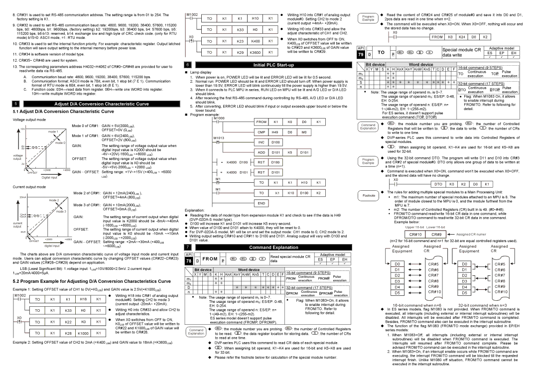
Voltage output mode
Mode 0 of CR#1:
10V |
| mode 1 |
| |
|
| Mode 1 of CR#1: | ||
|
|
|
| |
|
|
| mode 0 | GAIN: |
6V | GAIN |
|
| |
5V |
|
|
| |
|
|
|
| |
voltage |
|
|
| OFFSET: |
output |
|
|
| |
2V |
|
|
|
|
0 | OFFSET | +2000 | +4000 | GAIN-OFFSET: |
Digital input
GAIN = 5V(2000LSB),
OFFSET=0V (0LSB)
GAIN = 6V(2400LSB),
OFFSET=2V (800LSB).
The setting range of voltage output value when digital input value is K2000 should be
The setting range of voltage output value when digital input value is K0 should be
Setting range: +1V~+15V (+400LSB ~ +6000
LSB).
M1000 |
|
| FROM | K1 | K0 | D0 | K1 |
|
|
| |||||
|
|
| CMP | H49 | D0 | M0 |
|
M1013 |
|
|
|
|
|
|
|
|
|
| INC | D100 |
|
|
|
|
|
| ADD | D101 | K5 | D101 |
|
= | K4000 | D100 | RST | D100 |
|
|
|
= | K4000 | D101 | RST | D101 |
|
|
|
M1 |
|
| TO | K1 | K1 | H10 | K1 |
|
|
|
| execution command (TOP, DTOP) |
|
|
| ||||
Command |
|
| : the module number you are | probing. | : the | number of Controlled | ||
Explanation | Registers that will be written to. | : the data to write. | : the number of CRs | |||||
| to write to one time. |
|
|
| ||||
| ||||||||
| special modules. |
|
|
| ||||
|
| : When assigning bit operand, K1~K4 are used for | ||||||
| used for |
|
|
| ||||
Program | Using the | |||||||
Example | and CR#2 of special module#0. DTO only allows one group of data to be written at | |||||||
| a time (n=1). |
|
|
| ||||
| Command is executed when X0=ON, command won’t be executed when X0=OFF, | |||||||
| and the stored data will have no change. |
|
| |||||
|
| X0 |
|
|
| |||
|
|
|
|
| DTO | K0 |
|
|
|
|
|
|
|
| |||
Current output mode |
|
|
|
|
|
|
|
| |||||||||||||||
|
|
|
|
|
|
|
|
|
|
|
|
|
|
|
|
|
|
|
|
|
| Mode 2 of CR#1: GAIN = 12mA(2400LSB ), | |
| 20mA |
|
|
|
|
|
|
|
|
|
|
|
|
|
|
|
|
|
|
|
| OFFSET=4mA (800LSB). | |
|
|
|
|
|
|
|
|
|
|
|
| mode 2 |
|
|
| ||||||||
|
|
|
|
|
|
|
|
|
|
|
|
|
|
|
|
|
| ||||||
|
|
|
|
|
|
|
|
|
|
|
|
|
|
|
|
|
|
|
|
|
| Mode 3 of CR#1: GAIN = 10mA(2000LSB), | |
|
|
|
|
|
|
|
|
|
|
|
|
|
|
|
| mode 3 |
|
|
| OFFSET=0mA (0LSB). | |||
| 12mA |
|
|
|
|
|
|
|
|
|
|
|
|
|
|
|
| ||||||
|
|
|
|
|
|
|
|
|
|
|
|
|
|
|
|
|
|
|
|
|
| ||
| 10mA | GAIN |
|
|
|
|
|
|
|
|
|
|
| GAIN: | The setting range of current output when digital | ||||||||
|
|
|
|
|
|
|
|
|
|
|
|
|
|
|
|
|
|
|
| ||||
|
|
|
|
|
|
|
|
|
|
|
|
|
|
|
|
|
|
|
|
|
|
| input value is K2000 should be |
current |
|
|
|
|
|
|
|
|
|
|
|
|
|
|
|
|
|
|
|
| |||
|
|
|
|
|
|
|
|
|
|
|
|
|
|
|
|
|
|
|
| ||||
output |
|
|
|
|
|
|
|
|
|
|
|
|
|
|
|
|
|
|
| OFFSET: | |||
| 4mA |
|
|
|
|
|
|
|
|
|
|
|
|
|
|
|
|
|
|
| The setting range of current output when digital | ||
|
|
|
|
|
|
|
|
|
|
|
|
|
|
|
|
|
|
|
|
| input value is K0 should be | ||
|
|
|
|
|
|
|
|
|
|
|
|
|
|
|
|
|
|
|
|
|
|
| |
|
| 0 | OFFSET | +2000 | +4000 |
| |||||||||||||||||
|
|
|
|
|
|
|
|
|
|
|
|
|
| GAIN-OFFSET: | Setting range: +2mA~+30mA (+400LSB | ||||||||
|
|
|
|
|
|
|
|
|
|
|
|
|
|
|
|
|
|
|
|
|
| ||
M1 |
| K10 D100 | K2 | |||
|
|
| TO | K1 | ||
|
|
| ||||
|
|
| END |
|
|
|
|
|
|
|
|
| |
Explanation:
Reading the data of model type from expansion module K1 and check to see if the data is H49
D100 will increase K1 and D101 will increase K5 every second. When value of D100 and D101 attain to K4000, they will be reset to 0.
For
Footnote | The rules for adding multiple special modules to a Main Processing Unit: | |
m1: The maximum number of special modules attached to an MPU is 8. The | ||
| ||
| order of module closest to the MPU is 0, and the module furthest from the | |
| MPU is 7. | |
| m2: The number of Controlled Registers (CR) built in is 49. (#0~#48). | |
| FROM/TO command read/write | |
| DFROM/DTO command to read/write | |
| Example below: | |
| Upper |
Assigned CR numer
(n=2 for
digital input | ~+6000LSB). |
The charts above are D/A conversion characteristic curve of voltage input mode and current input mode. Users can adjust conversion characteristic curve by changing OFFSET values (CR#22~CR#23) and GAIN values (CR#28~CR#29) depend on application.
LSB (Least Significant Bit): 1.voltage input: 1LSB=10V/8000=2.5mV. 2.current input: 1LSB=20mA/4000=5µA.
5.2 Program Example for Adjusting D/A Conversion Characteristics Curve
Example 1: Setting OFFSET value of CH1 to 0V(=K0LSB) and GAIN value is 2.5V(=K1000LSB).
M1002 | K1 | K1 | H18 | K1 | Writing H18 into CR#1 of analog output | ||||
|
|
|
| TO | module#0. Setting CH2 to mode 3 | ||||
|
|
| |||||||
|
| ||||||||
|
|
|
|
|
|
|
|
| (current output |
| 7 |
|
|
|
|
|
|
|
|
|
|
|
|
|
|
| Command Explanation |
|
|
|
|
|
|
|
|
|
| ||||||||||
|
|
|
|
|
|
|
|
|
|
|
|
|
|
|
|
|
|
|
|
|
|
|
|
|
| ||||||||||||
|
|
|
|
|
|
|
|
|
|
|
|
|
|
|
|
|
|
|
|
|
|
|
|
|
|
|
|
|
|
|
|
|
|
|
|
|
|
|
|
|
|
|
|
|
|
|
|
|
|
|
|
|
|
|
|
|
|
|
|
|
|
|
|
|
|
|
|
|
|
|
|
|
|
|
|
| API |
|
|
|
|
| FROM |
|
|
|
|
|
|
|
|
| Read special module CR |
|
| Adaptive model |
| ||||||||||||||||
| 78 |
|
|
|
|
|
|
|
|
|
|
|
|
|
|
|
| ES |
|
| EP | EH |
| ||||||||||||||
|
|
| D |
|
|
| P |
|
|
|
|
|
|
| data |
|
|
|
|
|
|
| |||||||||||||||
|
|
|
|
|
|
|
|
|
|
|
|
|
|
|
|
|
|
|
|
|
|
|
|
|
|
|
|
| |||||||||
|
|
|
|
|
|
|
|
|
|
|
|
|
|
|
|
|
|
|
|
|
|
|
|
|
|
|
|
|
|
|
|
|
|
|
|
|
|
|
|
|
|
|
|
|
|
|
|
|
|
|
|
|
|
|
|
|
|
|
|
|
|
|
|
|
|
|
|
|
|
|
|
|
| ||
|
|
|
| Bit device |
|
|
|
|
|
| Word device |
|
|
|
|
|
|
|
|
| |||||||||||||||||
|
|
| X | Y | M | S | K |
| H | KnX | KnY | KnM | KnS | T | C | D | E | F |
|
|
|
| |||||||||||||||
|
|
|
|
|
|
|
|
|
|
|
|
|
|
|
|
|
|
| FROM Continuous | FROM |
|
|
| Pulse |
| ||||||||||||
| m1 |
|
|
|
| ¼ | ¼ |
|
|
|
|
|
|
|
|
|
| P |
| ||||||||||||||||||
|
|
|
|
|
|
|
|
|
|
|
|
|
|
|
|
|
|
|
|
|
|
|
|
|
| execution |
|
|
|
|
|
|
| execution |
| ||
| m2 |
|
|
|
|
|
|
| ¼ | ¼ |
|
|
|
|
|
|
|
|
|
|
|
|
|
|
|
|
|
| |||||||||
|
|
|
|
|
|
|
|
|
|
|
|
|
|
|
|
|
|
| |||||||||||||||||||
| D |
|
|
|
|
|
|
|
|
|
|
|
|
| ¼ | ¼ | ¼ | ¼ | ¼ | ¼ | ¼ | ¼ |
|
|
|
| |||||||||||
| n |
|
|
|
| ¼ | ¼ |
|
|
|
|
|
|
|
|
|
|
|
| Continuous |
|
|
|
|
|
|
| Pulse |
| ||||||||
|
|
|
|
|
|
|
|
|
|
|
|
|
|
|
|
|
|
|
|
|
|
|
|
| D | FROM execution |
| D | FROM | P | execution |
| |||||
|
|
|
|
|
| Note: The usage range of operand m1 is 0~7. |
|
|
| ||||||||||||||||||||||||||||
|
|
|
|
|
|
|
|
|
|
| |||||||||||||||||||||||||||
|
|
|
|
|
|
|
| Flag: When M1083=On, it allows |
| ||||||||||||||||||||||||||||
|
|
|
|
|
|
|
|
| The usage range of operand m2: ES/EP: |
|
|
| |||||||||||||||||||||||||
|
|
|
|
|
|
|
|
| EH: |
|
|
|
|
|
|
|
|
|
| to enable interrupt during |
| ||||||||||||||||
Assigned | Assigned | ||
Equipment | CR | ||
D0 |
|
| CR#5 |
|
| ||
|
| ||
D1 |
|
| CR#6 |
|
| ||
D2 |
|
| CR#7 |
|
| ||
D3 |
|
| CR#8 |
|
| ||
D4 |
|
| CR#9 |
|
| ||
D5 |
|
| CR#10 |
|
| ||
|
|
|
|
Assigned |
|
| Assigned | |||||
Equipment |
|
| CR | |||||
D0 |
|
|
|
|
|
|
| CR#5 |
|
|
|
|
|
|
| ||
|
|
|
| |||||
D1 |
|
|
|
|
|
| CR#6 | |
|
|
|
| |||||
D2 |
|
|
|
|
|
| CR#7 | |
|
|
|
| |||||
D3 |
|
|
|
|
|
| CR#8 | |
|
|
|
| |||||
D4 |
|
|
|
|
|
| CR#9 | |
|
|
|
| |||||
D5 |
|
|
|
|
|
| CR#10 | |
|
|
|
| |||||
|
|
|
|
|
|
|
|
|
|
|
|
|
| TO | K1 | K33 | H0 | K1 | Writing H0 into CR#33 and allow CH2 to |
|
|
|
|
| ||||||
X0 |
|
|
|
| adjust characteristics. | |||||
K1 | K22 | K0 | K1 | When X0 switches from OFF to ON, | ||||||
|
|
|
|
| TO | K0LSB of OFFSET value will be written to | ||||
|
|
|
|
| ||||||
|
|
|
|
|
|
|
|
|
| |
|
|
|
|
|
|
|
|
|
| CR#22 and K1000LSB of GAIN value will |
|
|
|
|
| TO | K1 | K28 | K1000 | K1 | be written to CR#28. |
|
|
|
|
| ||||||
Example 2: Setting OFFSET value of CH2 to 2mA (=K400 LSB) and GAIN value to 18mA (=K3600LSB).
| The usage range of operand n: ES/EP: n= | FROM/TO. Refer to | ||
| following for detail. | |||
| ES series model doesn’t support pulse |
|
| |
| execution command (FROMP, DFROMP). |
|
| |
Command | : the module number you are probing. | : the number of Controlled Registers | ||
Explanation | to be read. | : the data register location for storing data. | : the number of CRs | |
to read at one time.
![]() : When assigning bit operand, K1~K4 are used for
: When assigning bit operand, K1~K4 are used for
Please refer the footnote below for calculation of the special module number.
In ES series models, flag M1083 is not provided. When FROM/TO command is executed, all interrupts (including external or internal interrupt subroutines) will be disabled. All interrupts will be executed after FROM/TO command is completed. Besides, FROM/TO command also can be executed in the interrupt subroutine.
The function of the flag M1083 (FROM/TO mode exchange) provided in EP/EH series models:
1.When M1083=Off, all interrupts (including external or internal interrupt subroutines) will be disabled when FROM/TO command is executed. The Interrupts will resumed after FROM/TO command complete. Please be advised FROM/TO command can be executed in the interrupt subroutine.
2.When M1083=On, if an interrupt enable occurs while FROM/TO command are executing, the interrupt FROM/TO command will be blocked till the requested interrupt finish. Unlike M1080 off situation, FROM/TO command cannot be executed in the interrupt subroutine.