IPM24S0B0 specifications
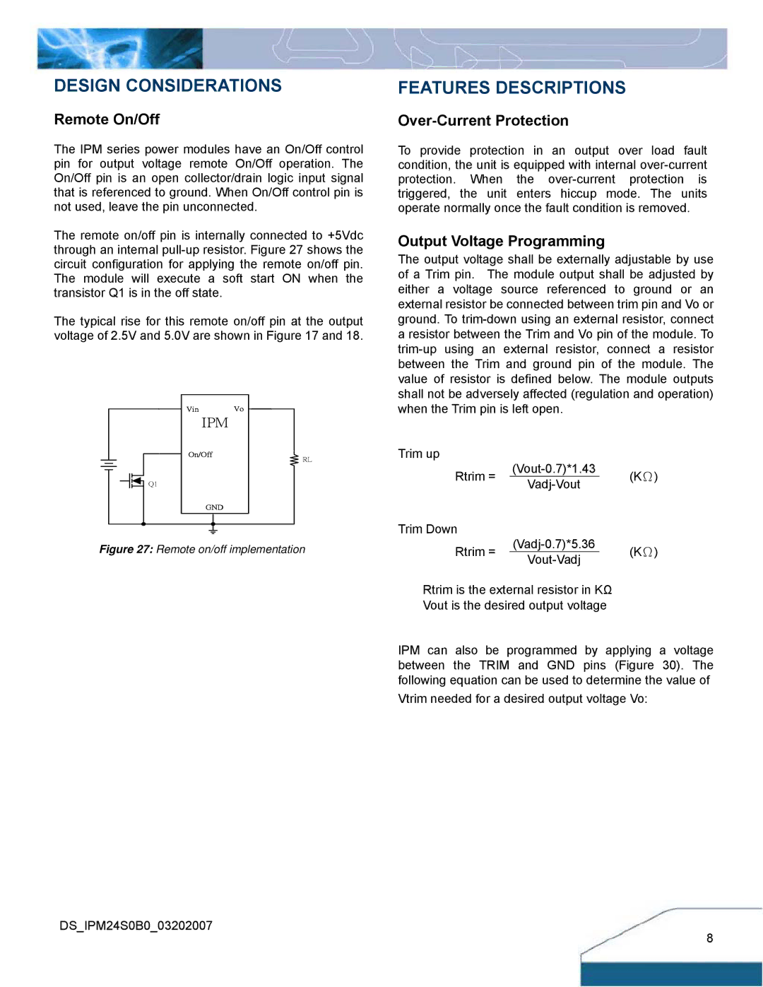
Delta Electronics has emerged as a key player in the field of power management and thermal solutions, and its IPM24S0B0 is an exemplary product demonstrating their commitment to innovation and efficiency. The IPM24S0B0 is an intelligent power module (IPM) that is designed for use in various applications, including motor drives, UPS systems, and renewable energy solutions.One of the main features of the IPM24S0B0 is its compact size, which makes it suitable for space-constrained applications. The integrated design combines the main components needed for power conversion in a single package, significantly reducing the footprint required on the printed circuit board (PCB). This modular design not only simplifies the circuitry but also enhances the overall reliability by minimizing interconnections.
The IPM24S0B0 utilizes cutting-edge technology, such as IGBT (Insulated Gate Bipolar Transistor) switching devices and built-in gate drivers, offering improved performance and lower switching losses. This translates to higher efficiency in various applications, which is essential in modern energy-conscious designs. The module is designed to operate efficiently at high frequencies, making it suitable for high-performance applications where speed and reliability are paramount.
Another significant characteristic of the IPM24S0B0 is its robust thermal management capabilities. The module features advanced thermal dissipation technologies, allowing it to maintain optimal operating temperatures even under heavy loads. This aspect of the design ensures prolonged component life and enhances system reliability, reducing the need for frequent maintenance or replacement.
The IPM24S0B0 also showcases excellent protection features, including short-circuit protection, over-temperature protection, and fault signaling mechanisms. These safety features are crucial for preventing damage in demanding industrial applications, where unexpected conditions can lead to severe malfunctions.
In addition, the module is designed to be compatible with various control schemes, making it versatile for use in different applications, from industrial automation to renewable energy systems. The IPM24S0B0 is part of Delta's broader commitment to sustainable technology, as it promotes energy efficiency and reduces total system costs.
In conclusion, the Delta Electronics IPM24S0B0 stands out in the crowded market of power modules as a high-performance, reliable, and efficient solution for modern power management needs. Its compact design, advanced technologies, and robust performance characteristics make it an ideal choice for engineers and designers looking to deliver cutting-edge solutions in their respective fields.

