2
PG Card and Pulse Generator
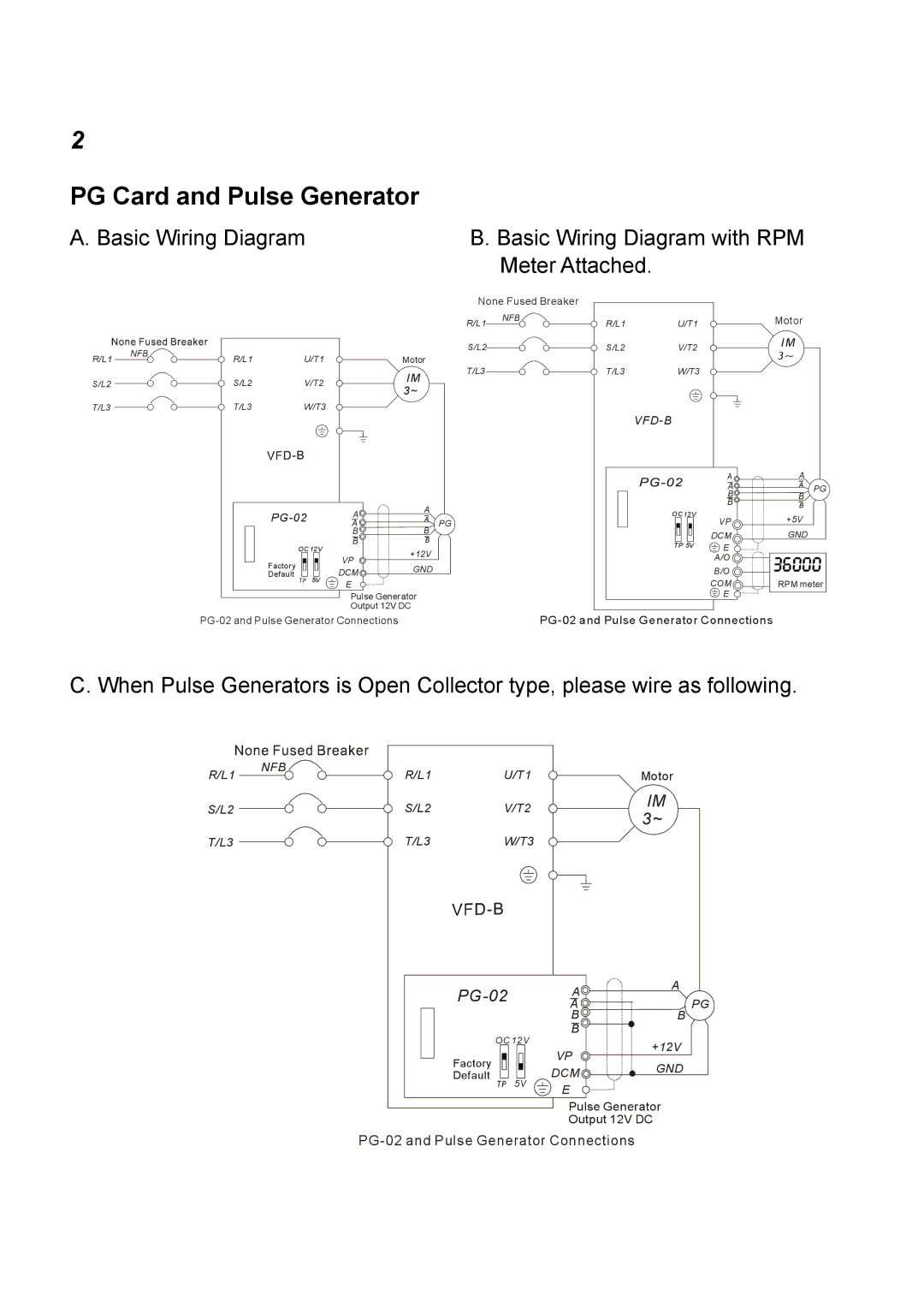
A. Basic Wiring Diagram | B. Basic Wiring Diagram with RPM |
| Meter Attached. |
R/L1 NFB![]()
S/L2
T/L3
R/L1 U/T1
S/L2 V/T2
T/L3 W/T3
None Fused Breaker
R/L1 | NFB | R/L1 | U/T1 | Motor |
|
| S/L2 | S/L2 | V/T2 | IM |
| 3~ | |||
Motor |
|
|
| |
T/L3 |
|
|
| |
IM | T/L3 | W/T3 |
| |
|
|
|
| |
3~ |
|
|
|
|
VFD-B
PG-02
OC 12V
Factory ![]()
![]() Default TP 5V
Default TP 5V
A | A |
|
A |
| |
A | PG | |
B | B |
|
B | B |
|
VP | +12V |
|
|
|
DCM ![]() GND E
GND E
Pulse Generator
Output 12V DC
OC12V
TP 5V
A | A |
|
A | A | PG |
B | B | |
B | B |
|
VP | +5V |
|
DCM | GND |
|
E |
|
|
A/O |
|
|
B/O |
|
|
COM | RPM meter | |
E |
|
|
C. When Pulse Generators is Open Collector type, please wire as following.
R/L1 NFB![]()
S/L2
T/L3
R/L1 U/T1
S/L2 V/T2
T/L3 W/T3
OC 12V
Factory
Default TP 5V
Motor
IM 3~
A | A | |
PG | ||
A | ||
B | B | |
B |
| |
VP | +12V | |
|
DCM ![]()
![]()
![]()
![]() GND E
GND E ![]()
![]()
![]()
![]()
Pulse Generator
Output 12V DC