DESIGN CONSIDERATIONS
Input Source Impedance
The impedance of the input source connecting to the DC/DC power modules will interact with the modules and affect the stability. A low
Layout and EMC Considerations
Delta’s DC/DC power modules are designed to operate in a wide variety of systems and applications. For design assistance with EMC compliance and related PWB layout issues, please contact Delta’s technical support team. An external input filter module is available for easier EMC compliance design. Below is the reference design for an input filter tested with H48SA12025NN A to meet class B in CISSPR 22.
Schematic and Components List
+ | CY1 |
| Vin(+) Vo(+) |
|
|
|
|
| |
CX | CX1 | Cin | H48SA12025 | LOAD |
Vin |
| L2 | ||
L1 |
|
|
| |
- | CY1 |
|
| |
|
|
| ||
|
|
| CY |
|
CX is 4.7uF ceramic cap;
CX1 is 4.7uF ceramic cap;
CY is 3.3nF ceramic cap;
CY1 is 4.7nF ceramic cap;
L1 is
L2 is
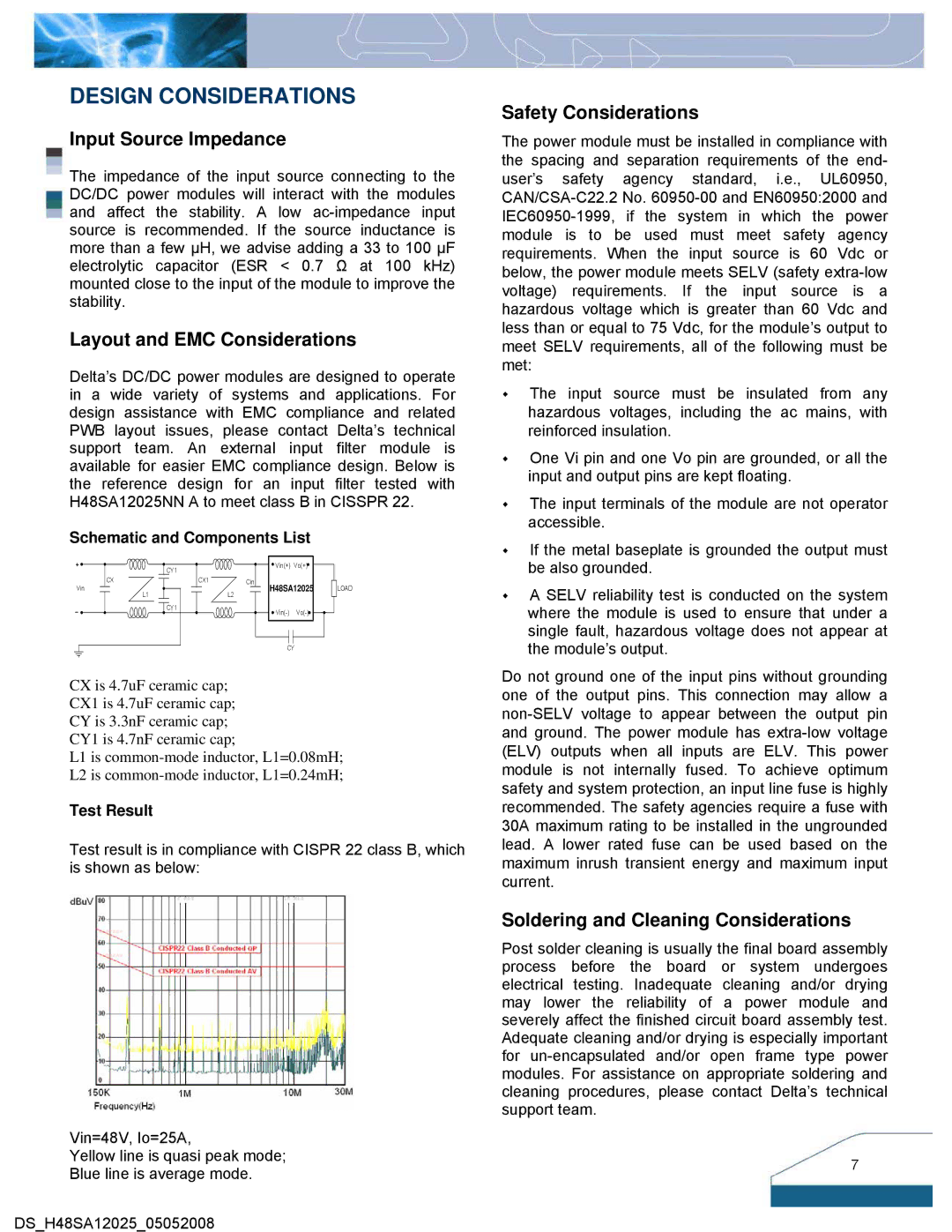
Test Result
Test result is in compliance with CISPR 22 class B, which is shown as below:
Vin=48V, Io=25A,
Yellow line is quasi peak mode;
Blue line is average mode.
DS_H48SA12025_05052008
Safety Considerations
The power module must be installed in compliance with the spacing and separation requirements of the end- user’s safety agency standard, i.e., UL60950,
The input source must be insulated from any hazardous voltages, including the ac mains, with reinforced insulation.
One Vi pin and one Vo pin are grounded, or all the input and output pins are kept floating.
The input terminals of the module are not operator accessible.
If the metal baseplate is grounded the output must be also grounded.
A SELV reliability test is conducted on the system where the module is used to ensure that under a single fault, hazardous voltage does not appear at the module’s output.
Do not ground one of the input pins without grounding one of the output pins. This connection may allow a
Soldering and Cleaning Considerations
Post solder cleaning is usually the final board assembly process before the board or system undergoes electrical testing. Inadequate cleaning and/or drying may lower the reliability of a power module and severely affect the finished circuit board assembly test. Adequate cleaning and/or drying is especially important for
7