6. Enhanced Digital Diagnostic Interface
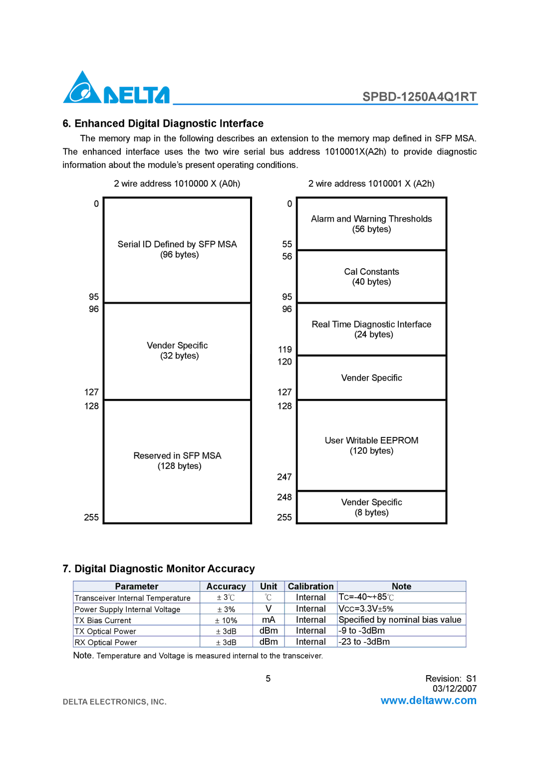
The memory map in the following describes an extension to the memory map defined in SFP MSA. The enhanced interface uses the two wire serial bus address 1010001X(A2h) to provide diagnostic
information about the module’s present operating conditions.
| 2 wire address 1010000 X (A0h) |
| |
0 |
| 0 | |
Serial ID Defined by SFP MSA | |||
| 55 | ||
| (96 bytes) | 56 | |
95 |
| 95 | |
96 | Vender Specific | 96 | |
| 119 | ||
| (32 bytes) | ||
| 120 | ||
|
| ||
127 |
| 127 | |
128 | Reserved in SFP MSA | 128 | |
|
| ||
| (128 bytes) | 247 | |
|
| ||
|
| 248 | |
255 |
| 255 |
2 wire address 1010001 X (A2h)
Alarm and Warning Thresholds
(56 bytes)
Cal Constants
(40 bytes)
Real Time Diagnostic Interface (24 bytes)
Vender Specific
User Writable EEPROM
(120 bytes)
Vender Specific
(8 bytes)
7. Digital Diagnostic Monitor Accuracy
Parameter | Accuracy | Unit | Calibration | Note |
Transceiver Internal Temperature | ± 3℃ | ℃ | Internal | |
Power Supply Internal Voltage | ± 3% | V | Internal | VCC=3.3V±5% |
TX Bias Current | ± 10% | mA | Internal | Specified by nominal bias value |
TX Optical Power | ± 3dB | dBm | Internal | |
RX Optical Power | ± 3dB | dBm | Internal |
Note. Temperature and Voltage is measured internal to the transceiver.
5 | Revision: S1 |
| 03/12/2007 |
DELTA ELECTRONICS, INC. | www.deltaww.com |
