1.17 Interface Board Diagnostic Chart
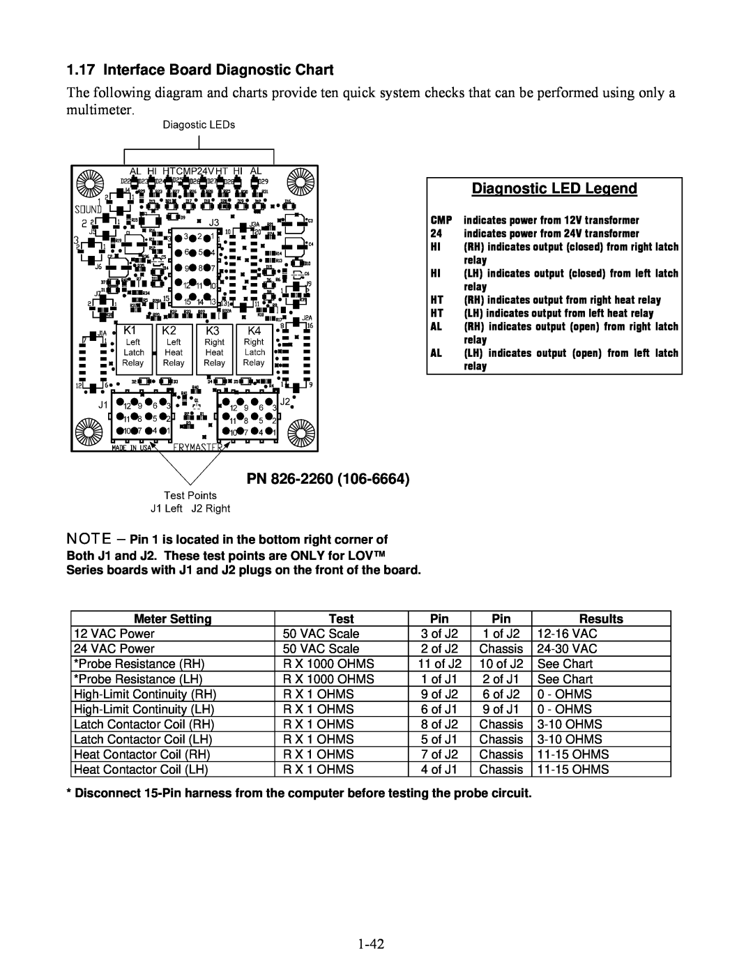
The following diagram and charts provide ten quick system checks that can be performed using only a multimeter.
| Diagnostic LED Legend |
CMP | indicates power from 12V transformer |
24 | indicates power from 24V transformer |
HI | (RH) indicates output (closed) from right latch |
| relay |
HI | (LH) indicates output (closed) from left latch |
| relay |
HT | (RH) indicates output from right heat relay |
HT | (LH) indicates output from left heat relay |
AL | (RH) indicates output (open) from right latch |
| relay |
AL | (LH) indicates output (open) from left latch |
| relay |
PN 826-2260 (106-6664)
NOTE – Pin 1 is located in the bottom right corner of
Both J1 and J2. These test points are ONLY for LOV™
Series boards with J1 and J2 plugs on the front of the board.
Meter Setting | Test | Pin | Pin | Results |
12 VAC Power | 50 VAC Scale | 3 of J2 | 1 of J2 | |
24 VAC Power | 50 VAC Scale | 2 of J2 | Chassis | |
*Probe Resistance (RH) | R X 1000 OHMS | 11 of J2 | 10 of J2 | See Chart |
*Probe Resistance (LH) | R X 1000 OHMS | 1 of J1 | 2 of J1 | See Chart |
R X 1 OHMS | 9 of J2 | 6 of J2 | 0 - OHMS | |
R X 1 OHMS | 6 of J1 | 9 of J1 | 0 - OHMS | |
Latch Contactor Coil (RH) | R X 1 OHMS | 8 of J2 | Chassis | |
Latch Contactor Coil (LH) | R X 1 OHMS | 5 of J1 | Chassis | |
Heat Contactor Coil (RH) | R X 1 OHMS | 7 of J2 | Chassis | |
Heat Contactor Coil (LH) | R X 1 OHMS | 4 of J1 | Chassis |
* Disconnect