1.13.3 Replacing an AIF (Automatic Intermittent Filtration) board
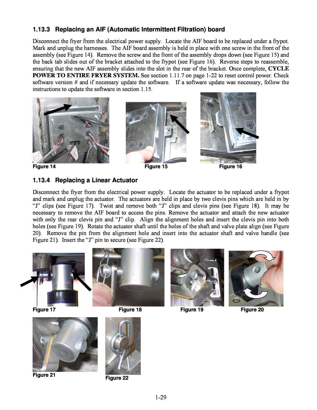
Disconnect the fryer from the electrical power supply. Locate the AIF board to be replaced under a frypot. Mark and unplug the harnesses. The AIF board assembly is held in place with one screw in the front of the assembly (see Figure 14). Remove the screw and the front of the assembly drops down (see Figure 15) and the back tab slides out of the bracket attached to the frypot (see Figure 16). Reverse steps to reassemble, ensuring that the new AIF assembly slides into the slot in the rear of the bracket. Once complete, CYCLE POWER TO ENTIRE FRYER SYSTEM. See section 1.11.7 on page
Figure 14 | Figure 15 | Figure 16 |
1.13.4 Replacing a Linear Actuator
Disconnect the fryer from the electrical power supply. Locate the actuator to be replaced under a frypot and mark and unplug the actuator. The actuators are held in place by two clevis pins which are held in by “J” clips (see Figure 17). Twist and remove both “J” clips and clevis pins (see Figure 18). It may be necessary to remove the AIF board to access the pins. Remove the actuator and attach the new actuator with only the rear clevis pin and “J” clip. Align the alignment holes and insert the clevis pin into both holes (see Figure 19). Rotate the actuator shaft until the holes of the shaft and valve plate align (see Figure 20). Remove the pin from the alignment hole and insert into the actuator shaft and valve handle (see Figure 21). Insert the “J” pin to secure (see Figure 22).
Figure 17 | Figure 18 | Figure 19 | Figure 20 |
Figure 21 | Figure 22 |
|