4.Locate the red (or yellow) and white wires of the temperature probe to be replaced. Note where the leads are connected prior to removing them from the connector. Unplug the 12-pin connector C-6 and using a pin-pusher push the pins of the temperature probe out of the connector.
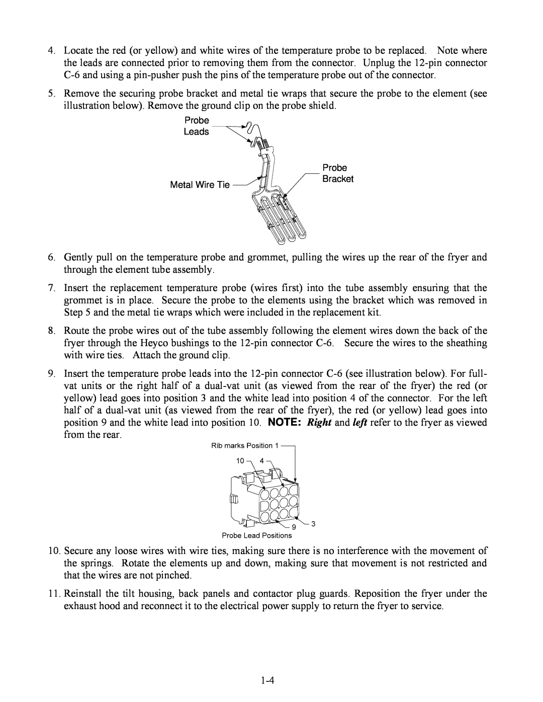
5.Remove the securing probe bracket and metal tie wraps that secure the probe to the element (see illustration below). Remove the ground clip on the probe shield.
Probe
Leads ![]()
![]()
| Probe |
Metal Wire Tie | Bracket |
|
6.Gently pull on the temperature probe and grommet, pulling the wires up the rear of the fryer and through the element tube assembly.
7.Insert the replacement temperature probe (wires first) into the tube assembly ensuring that the grommet is in place. Secure the probe to the elements using the bracket which was removed in Step 5 and the metal tie wraps which were included in the replacement kit.
8.Route the probe wires out of the tube assembly following the element wires down the back of the fryer through the Heyco bushings to the
9.Insert the temperature probe leads into the
10.Secure any loose wires with wire ties, making sure there is no interference with the movement of the springs. Rotate the elements up and down, making sure that movement is not restricted and that the wires are not pinched.
11.Reinstall the tilt housing, back panels and contactor plug guards. Reposition the fryer under the exhaust hood and reconnect it to the electrical power supply to return the fryer to service.