1.10.3 Replacing the ATO board, LON Gateway, ATO pump relay or Transformers
Disconnect the fryer from the electrical power supply. Locate the ATO box (see Figure 1 on page 12), behind the JIB (Jug In Box). Remove the cover to expose the transformers, relay and LON gateway (if installed) (see Figure 2). Mark and unplug any wires or harnesses. Once the LON gateway is removed the ATO board is visible (see Figure 3). Replace the defective component and reattach all wires or harnesses. Replace the cover. Once replaced, CYCLE POWER TO ENTIRE FRYER
SYSTEM. See section 1.11.7 on page
necessary update the software. If a software update was necessary, follow the instructions to update the software in section 1.15
Press the TEMP button on one of the M3000 computers, with the computer in the OFF position, to verify software version of the ATO. If the version is not visible, the ATO may not be connected properly.
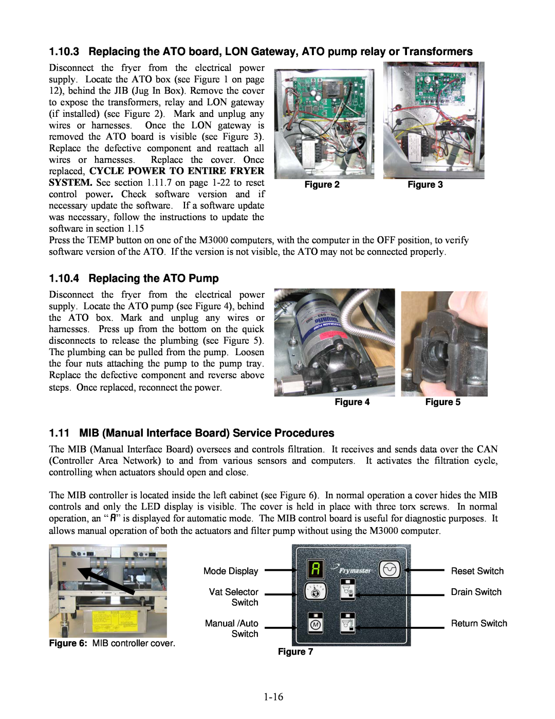
1.10.4 Replacing the ATO Pump
Disconnect the fryer from the electrical power supply. Locate the ATO pump (see Figure 4), behind the ATO box. Mark and unplug any wires or harnesses. Press up from the bottom on the quick disconnects to release the plumbing (see Figure 5). The plumbing can be pulled from the pump. Loosen the four nuts attaching the pump to the pump tray. Replace the defective component and reverse above steps. Once replaced, reconnect the power.
Figure 4 | Figure 5 |
1.11 MIB (Manual Interface Board) Service Procedures
The MIB (Manual Interface Board) oversees and controls filtration. It receives and sends data over the CAN (Controller Area Network) to and from various sensors and computers. It activates the filtration cycle, controlling when actuators should open and close.
The MIB controller is located inside the left cabinet (see Figure 6). In normal operation a cover hides the MIB controls and only the LED display is visible. The cover is held in place with three torx screws. In normal operation, an “A” is displayed for automatic mode. The MIB control board is useful for diagnostic purposes. It allows manual operation of both the actuators and filter pump without using the M3000 computer.
Mode Display | Reset Switch |
Vat Selector | Drain Switch |
Switch |
|
Manual /Auto | Return Switch |
Switch |
|
Figure 6: MIB controller cover. | Figure 7 |
|