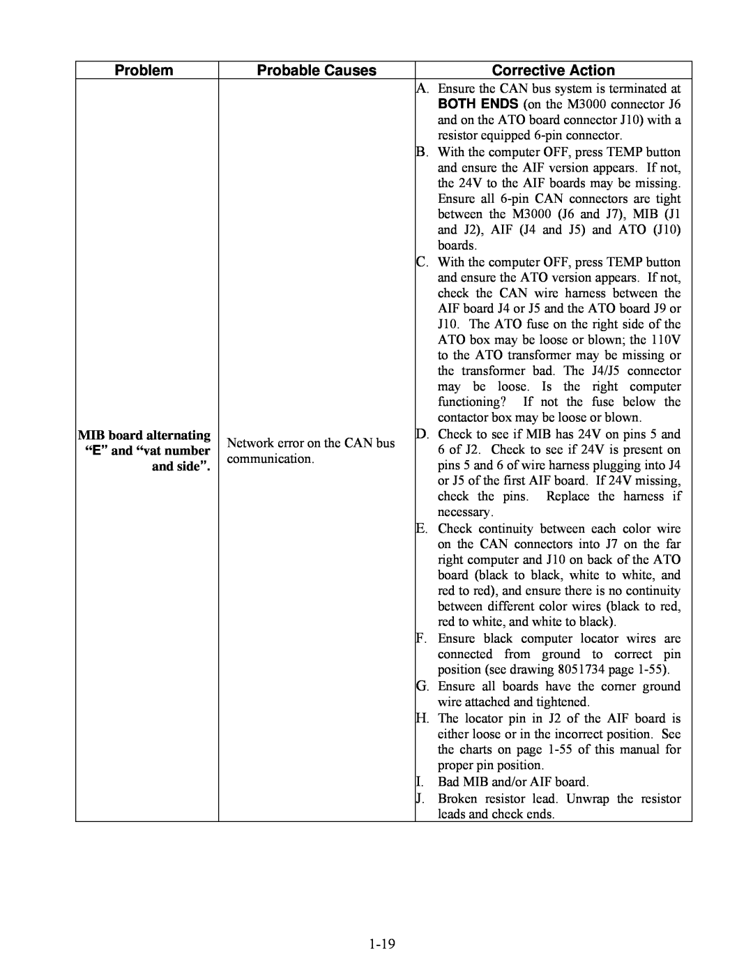
Problem | Probable Causes |
| Corrective Action |
|
| A. Ensure the CAN bus system is terminated at | |
|
|
| BOTH ENDS (on the M3000 connector J6 |
|
|
| and on the ATO board connector J10) with a |
|
|
| resistor equipped |
|
| B. With the computer OFF, press TEMP button | |
|
|
| and ensure the AIF version appears. If not, |
|
|
| the 24V to the AIF boards may be missing. |
|
|
| Ensure all |
|
|
| between the M3000 (J6 and J7), MIB (J1 |
|
|
| and J2), AIF (J4 and J5) and ATO (J10) |
|
|
| boards. |
|
| C. With the computer OFF, press TEMP button | |
|
|
| and ensure the ATO version appears. If not, |
|
|
| check the CAN wire harness between the |
|
|
| AIF board J4 or J5 and the ATO board J9 or |
|
|
| J10. The ATO fuse on the right side of the |
|
|
| ATO box may be loose or blown; the 110V |
|
|
| to the ATO transformer may be missing or |
|
|
| the transformer bad. The J4/J5 connector |
|
|
| may be loose. Is the right computer |
|
|
| functioning? If not the fuse below the |
|
|
| contactor box may be loose or blown. |
MIB board alternating | Network error on the CAN bus | D. Check to see if MIB has 24V on pins 5 and | |
“E” and “vat number |
| 6 of J2. Check to see if 24V is present on | |
communication. |
| ||
and side”. |
| pins 5 and 6 of wire harness plugging into J4 | |
|
| ||
|
|
| or J5 of the first AIF board. If 24V missing, |
|
|
| check the pins. Replace the harness if |
|
|
| necessary. |
|
| E. Check continuity between each color wire | |
|
|
| on the CAN connectors into J7 on the far |
|
|
| right computer and J10 on back of the ATO |
|
|
| board (black to black, white to white, and |
|
|
| red to red), and ensure there is no continuity |
|
|
| between different color wires (black to red, |
|
| F. | red to white, and white to black). |
|
| Ensure black computer locator wires are | |
|
|
| connected from ground to correct pin |
|
|
| position (see drawing 8051734 page |
|
| G. Ensure all boards have the corner ground | |
|
|
| wire attached and tightened. |
|
| H. The locator pin in J2 of the AIF board is | |
|
|
| either loose or in the incorrect position. See |
|
|
| the charts on page |
|
| I. | proper pin position. |
|
| Bad MIB and/or AIF board. | |
|
| J. | Broken resistor lead. Unwrap the resistor |
|
|
| leads and check ends. |
Page 26
Image 26
