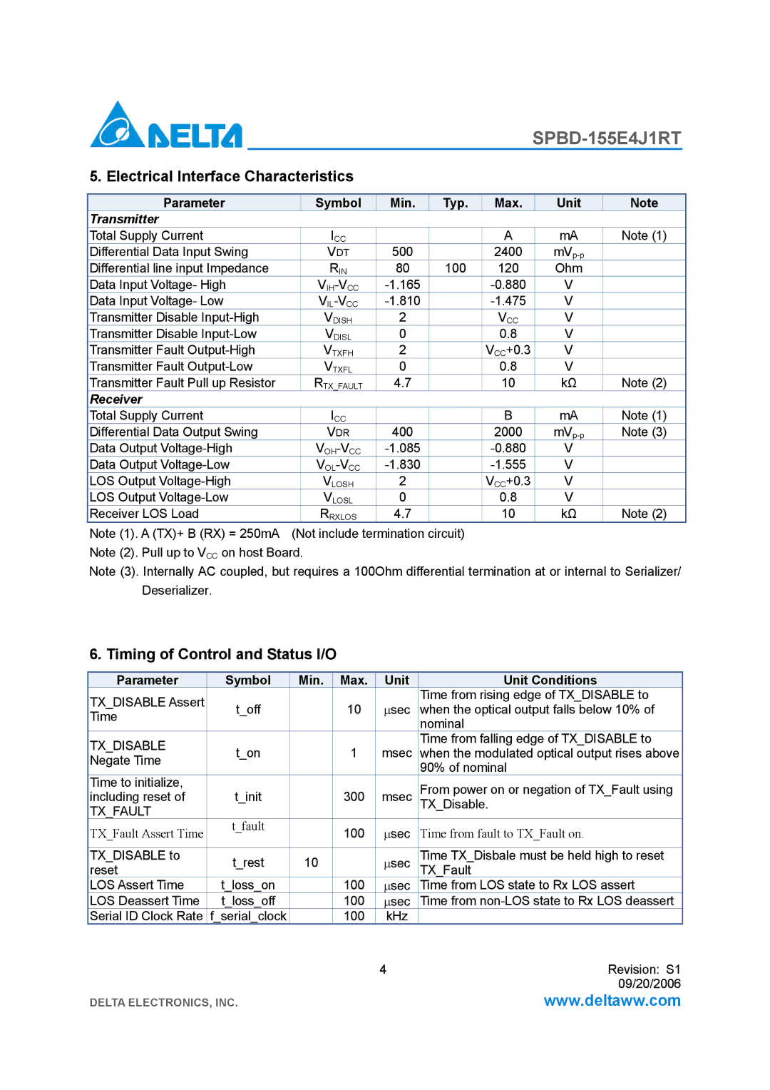
5. Electrical Interface Characteristics
Parameter |
| Symbol | Min. | Typ. | Max. | Unit | Note |
Transmitter |
|
|
|
|
|
|
|
Total Supply Current |
| ICC |
|
| A | mA | Note (1) |
Differential Data Input Swing |
| VDT | 500 |
| 2400 |
| |
Differential line input Impedance |
| RIN | 80 | 100 | 120 | Ohm |
|
Data Input Voltage- High |
|
| V |
| |||
Data Input Voltage- Low |
|
| V |
| |||
Transmitter Disable |
| VDISH | 2 |
| VCC | V |
|
Transmitter Disable |
| VDISL | 0 |
| 0.8 | V |
|
Transmitter Fault |
| VTXFH | 2 |
| VCC+0.3 | V |
|
Transmitter Fault |
| VTXFL | 0 |
| 0.8 | V |
|
Transmitter Fault Pull up Resistor |
| RTX_FAULT | 4.7 |
| 10 | kΩ | Note (2) |
Receiver |
|
|
|
|
|
|
|
Total Supply Current |
| ICC |
|
| B | mA | Note (1) |
Differential Data Output Swing |
| VDR | 400 |
| 2000 | Note (3) | |
Data Output |
|
| V |
| |||
Data Output |
|
| V |
| |||
LOS Output |
| VLOSH | 2 |
| VCC+0.3 | V |
|
LOS Output |
| VLOSL | 0 |
| 0.8 | V |
|
Receiver LOS Load |
| RRXLOS | 4.7 |
| 10 | kΩ | Note (2) |
Note (1). A (TX)+ B (RX) = 250mA | (Not include termination circuit) |
|
|
| |||
Note (2). Pull up to VCC on host Board.
Note (3). Internally AC coupled, but requires a 100Ohm differential termination at or internal to Serializer/ Deserializer.
6. Timing of Control and Status I/O
Parameter | Symbol | Min. | Max. | Unit | Unit Conditions |
TX_DISABLE Assert | t_off |
| 10 |
| Time from rising edge of TX_DISABLE to |
| ∝sec | when the optical output falls below 10% of | |||
Time |
| ||||
|
|
|
| nominal | |
|
|
|
|
| |
TX_DISABLE | t_on |
| 1 | msec | Time from falling edge of TX_DISABLE to |
| when the modulated optical output rises above | ||||
Negate Time |
| ||||
|
|
|
| 90% of nominal | |
|
|
|
|
| |
Time to initialize, | t_init |
| 300 | msec | From power on or negation of TX_Fault using |
including reset of |
| ||||
TX_FAULT |
|
|
|
| TX_Disable. |
|
|
|
|
| |
TX_Fault Assert Time | t_fault |
| 100 | ∝sec | Time from fault to TX_Fault on. |
|
| ||||
|
|
|
|
|
|
TX_DISABLE to | t_rest | 10 |
| ∝sec | Time TX_Disbale must be held high to reset |
reset |
| TX_Fault | |||
LOS Assert Time | t_loss_on |
| 100 | ∝sec | Time from LOS state to Rx LOS assert |
LOS Deassert Time | t_loss_off |
| 100 | ∝sec | Time from |
Serial ID Clock Rate | f_serial_clock |
| 100 | kHz |
|
|
|
|
| 4 | Revision: S1 |
|
|
|
|
| 09/20/2006 |
DELTA ELECTRONICS, INC. |
|
|
| www.deltaww.com | |