ENGLISH
2We greatly appreciate your purchase of the
2To be sure you take maximum advantage of all the features the
“SERIAL NO.
PLEASE RECORD UNIT SERIAL NUMBER ATTACHED TO THE REAR OF THE CABINET FOR FUTURE REFERENCE”
2INTRODUCTION
Thank you for choosing the DENON
As this product is provided with an immense array of features, we recommend that before you begin hookup and operation that you review the contents of this manual before proceeding.
1BEFORE USING
Pay attention to the following before using this unit:
•Moving the set
To prevent short circuits or damaged wires in the connection cords, always unplug the power cord and disconnect the connection cords between all other audio components when moving the set.
•Before turning the power switch on
Check once again that all connections are proper and that there are not problems with the connection cords. Always set the power switch to the standby position before connecting and disconnecting connection cords.
•Store this instructions in a safe place.
After reading, store this instructions along with the warranty in a safe place.
•Note that the illustrations in this instructions may differ from the actual set for explanation purposes.
TABLE OF CONTENTS
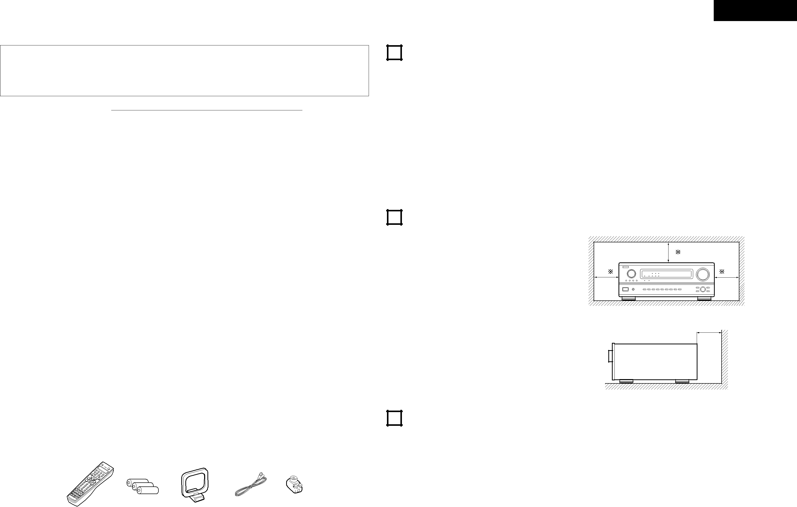
2CAUTIONS ON INSTALLATION
Noise or disturbance of the picture may be generated |
if this unit or any other electronic equipment using |
10 cm or more |
z Before Using........................................................ | 3 |
x Cautions on Installation........................................ | 3 |
c Cautions on Handling........................................... | 3 |
v Features ............................................................... | 4 |
b Connections..................................................... | 4~8 |
n Part Names and Functions .............................. | 8, 9 |
m Setting up the system................................... | 9~16 |
, Remote Control Unit ................................... | 16~22 |
. Operation..................................................... | 22~26 |
⁄0Surround ...................................................... | 27~29 |
⁄1DSP Surround Simulation ............................ | 30~32 |
⁄2Listening to the Radio ................................. | 33~35 |
⁄3Last Function Memory....................................... | 36 |
⁄4Initialization of the Microprocessor.................... | 36 |
⁄5Troubleshooting ........................................... | 36, 37 |
⁄6Additional Information ................................. | 37~41 |
⁄7Specifications..................................................... | 42 |
microprocessors is used near a tuner or TV. |
| ||
If this happens, take the following steps: |
| B | |
• Install this unit as far as possible from the tuner or |
| ||
TV. |
|
| |
• Set the antenna wires from the tuner or TV away |
| ||
from this unit’s power cord and input/output |
| ||
connection cords. |
|
| |
• Noise or disturbance tends to occur | particularly | 10 cm or more | |
when using indoor antennas or 300 Ω /ohms feeder | |||
| |||
wires. We recommend using outdoor antennas |
| ||
and 75 Ω /ohms coaxial cables. |
|
| |
wall
2ACCESSORIES
Check that the following parts are included in addition to the main unit:
For heat dispersal, leave at least 10 cm of space between the top, back and sides of this unit and the wall or other components.
q Operating instructions........................................ |
| 1 | t AM loop antenna................................................ | 1 | |
w Service station list.............................................. | 1 | y FM indoor antenna............................................. | 1 | ||
e Remote control unit | 1 | u FM antenna adaptor........................................... | 1 | ||
r R6P/AA batteries................................................ | 3 |
|
|
| |
e | r |
| t | y | u |
|
|
|
|
|
|
3CAUTIONS ON HANDLING
•Switching the input function when input jacks are not connected
A clicking noise may be produced if the input function is switched when nothing is connected to the input jacks. If this happens, either turn down the MASTER VOLUME control or connect components to the input jacks.
•Muting of PRE OUT jacks, HEADPHONE jacks and SPEAKER terminals
The PRE OUT jacks, HEADPHONE jacks and SPEAKER terminals include a muting circuit. Because of this, the output signals are greatly reduced for several seconds after the power switch is turned on or input function, surround mode or any
until the muting circuit turns off before adjusting the volume.
•Whenever the power switch is in the £ OFF state, the apparatus is still connected on AC line voltage.
Please be sure to unplug the cord when you leave home for, say, a vacation.
3