
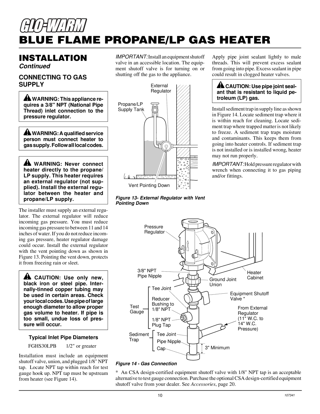
FGHS30LPB specifications
The Desa FGHS30LPB is a premium gas fireplace heater that combines style, efficiency, and modern technology to create a cozy and inviting atmosphere in any space. Designed with the contemporary homeowner in mind, this fireplace unit offers a unique blend of functionality and aesthetic appeal.One of the standout features of the FGHS30LPB is its heating capacity. With a powerful output of up to 30,000 BTUs, this gas heater is capable of warming an area of approximately 1,200 square feet. This makes it an ideal choice for both large rooms and open-concept living spaces, ensuring that comfort is always within reach, even on the coldest days.
The FGHS30LPB showcases a sleek glass front that enhances its modern design while allowing for an unobstructed view of the beautiful flames. This glass is not only visually appealing but also contributes to the unit's efficient heating performance. The large viewing area allows for maximum heat transfer and real-time enjoyment of the dancing flames, making it the perfect focal point in any room.
Another key characteristic of the FGHS30LPB is its ceramic fiber logs, which mimic the look of real wood, providing an authentic fireplace experience without the hassle of traditional wood-burning stoves. Complemented by realistic glowing embers, this design results in a visually stunning display that brings warmth and charm to any interior space.
Technologically, the FGHS30LPB excels with its electronic ignition system. This feature allows for easy start-up with the simple push of a button, eliminating the need for matches or lighters. In addition, the unit is equipped with a built-in thermostat control that helps maintain the desired temperature, ensuring consistent comfort while optimizing fuel consumption.
Safety is also a priority for the FGHS30LPB, which includes features such as automatic shut-off and a protective screen. These aspects ensure that users can enjoy the warmth and ambiance of the fireplace without concern.
Overall, the Desa FGHS30LPB is an exceptional choice for anyone seeking an efficient and stylish gas fireplace heater. With its impressive heating capabilities, realistic flame appearance, and modern technology, it is designed to enhance both comfort and aesthetics in your home. Whether for daily use or special occasions, this fireplace unit offers a blend of performance and elegance, making it an outstanding addition to any household.