Manuals
/
Desa
/
Household Appliance
/
Electric Heater
Desa
R 15 E UK
owner manual
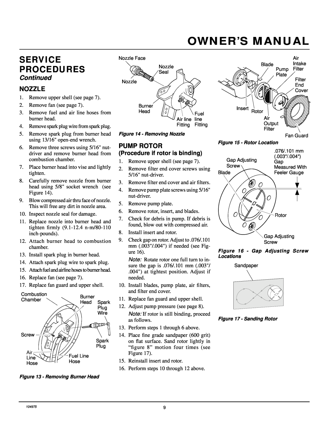
Nozzle, Pump Rotor, Service Procedures, Continued
Models:
R 15 E UK
1
9
14
14
Download
14 pages
10.76 Kb
6
7
8
9
10
11
12
13
Troubleshooting
Specification
Parts list
Maintenance
Motor and Pump Assembly
Pump Pressure Adjustment
Safety
Service Procedures
Page 9
Image 9
Page 8
Page 10
Page 9
Image 9
Page 8
Page 10
Contents
Heater Size 50,000 Btu/Hr Model R 15 E UK
PORTABLE FORCED AIR HEATER
SAFETY INFORMATION
R 15 E UK PORTABLE FORCED AIR HEATER
WARNINGS
UNPACKING
PRODUCT IDENTIFICATION
THEORY OF OPERATION
FUELS
VENTILATION
R 15 E UK PORTABLE FORCED AIR HEATER
OPERATION
MAINTENANCE
STORING, TRANSPORTING, OR SHIPPING
PREVENTATIVE
See Pump Pressure Adjustment, page
TROUBLESHOOTING
See Pump Pressure Adjustment, page
R 15 E UK PORTABLE FORCED AIR HEATER
SERVICE PROCEDURES
UPPER SHELL REMOVAL
AIR OUTPUT, AIR INTAKE, AND LINT FILTERS
Continued
PUMP PRESSURE ADJUSTMENT
FUEL FILTER
SPARK PLUG
PUMP ROTOR
NOZZLE
SERVICE PROCEDURES
Continued
PARTS
ILLUSTRATED
BREAKDOWN
R 15 E UK
R 15 E UK
PARTS LIST
PART
PART
WIRING DIAGRAM
SPECIFICATIONS
ACCESSORIES
AIR GAUGE KIT - HA1180
EC CONFORMITY DECLARATION
EQUIPMENT - LIMITED 1 YEAR WARRANTY
WARRANTY AND REPAIR SERVICE
WARRANTY SERVICE
CERTIFICATE OF GENERAL
Top
Page
Image
Contents