OWNERS MANUAL
OPERATING
HEATER
Continued
VARIABLE CONTROL
OPERATION
The variable control valve can be set to any heat setting and flame height desired, by simply turning the control knob until that setting is attained. Even the lowest setting provides realistic flames and glow- ing embers from two burners. Selecting higher settings produces greater heat output. This results in increased heating comfort.
![]() WARNING: Do not operate heater between locked positions.
WARNING: Do not operate heater between locked positions.
![]() CAUTION: Do not try to ad- just heating levels by using the equipment shutoff valve.
CAUTION: Do not try to ad- just heating levels by using the equipment shutoff valve.
TO TURN OFF GAS
TO APPLIANCE
Shutting Off Heater
1.Press in and turn control knob clock- wise Clockwise![]() to the HIGH position.
to the HIGH position.
2.Turn the control knob clockwise Clockwise![]() to the PILOT position.
to the PILOT position.
3.Press in control knob and turn clock- wise Clockwise![]() to the OFF Position.
to the OFF Position.
Shutting Off Burners Only (pilot stays lit)
1.Turn the control knob clockwise Clockwise![]() to the HIGH position.
to the HIGH position.
2.Press in and turn control knob clock- wise Clockwise![]() to the pilot position.
to the pilot position.
MANUAL LIGHTING
PROCEDURE
1.Follow steps 1 through 5 under Light- ing Instructions, page 14.
2.Depress control knob and light pilot with match.
3.Keep control knob pressed in for 30 seconds after lighting pilot. After 30 seconds, release control knob. Now follow step 8 under Lighting Instruc- tions, page 14.
INSPECTING
BURNERS
Check pilot flame pattern and burner flame patterns often.
PILOT FLAME PATTERN
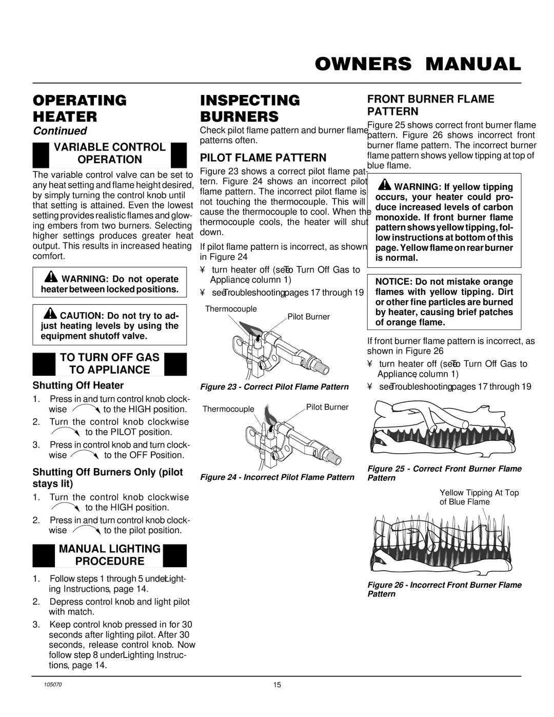
Figure 23 shows a correct pilot flame pat- tern. Figure 24 shows an incorrect pilot flame pattern. The incorrect pilot flame is not touching the thermocouple. This will cause the thermocouple to cool. When the thermocouple cools, the heater will shut down.
If pilot flame pattern is incorrect, as shown in Figure 24
•turn heater off (see To Turn Off Gas to Appliance, column 1)
•seeTroubleshooting, pages 17 through 19
Thermocouple
Pilot Burner
Figure 23 - Correct Pilot Flame Pattern
Thermocouple | Pilot Burner |
Figure 24 - Incorrect Pilot Flame Pattern
FRONT BURNER FLAME PATTERN
Figure 25 shows correct front burner flame pattern. Figure 26 shows incorrect front burner flame pattern. The incorrect burner flame pattern shows yellow tipping at top of blue flame.
![]() WARNING: If yellow tipping occurs, your heater could pro- duce increased levels of carbon monoxide. If front burner flame pattern shows yellow tipping, fol- low instructions at bottom of this page. Yellow flame on rear burner is normal.
WARNING: If yellow tipping occurs, your heater could pro- duce increased levels of carbon monoxide. If front burner flame pattern shows yellow tipping, fol- low instructions at bottom of this page. Yellow flame on rear burner is normal.
NOTICE: Do not mistake orange flames with yellow tipping. Dirt or other fine particles are burned by heater, causing brief patches of orange flame.
If front burner flame pattern is incorrect, as shown in Figure 26
•turn heater off (see To Turn Off Gas to Appliance, column 1)
•seeTroubleshooting, pages 17 through 19
Figure 25 - Correct Front Burner Flame Pattern
Yellow Tipping At Top
of Blue Flame
Figure 26 - Incorrect Front Burner Flame Pattern
105070 | 15 |
