Fireplace Installation
Continued
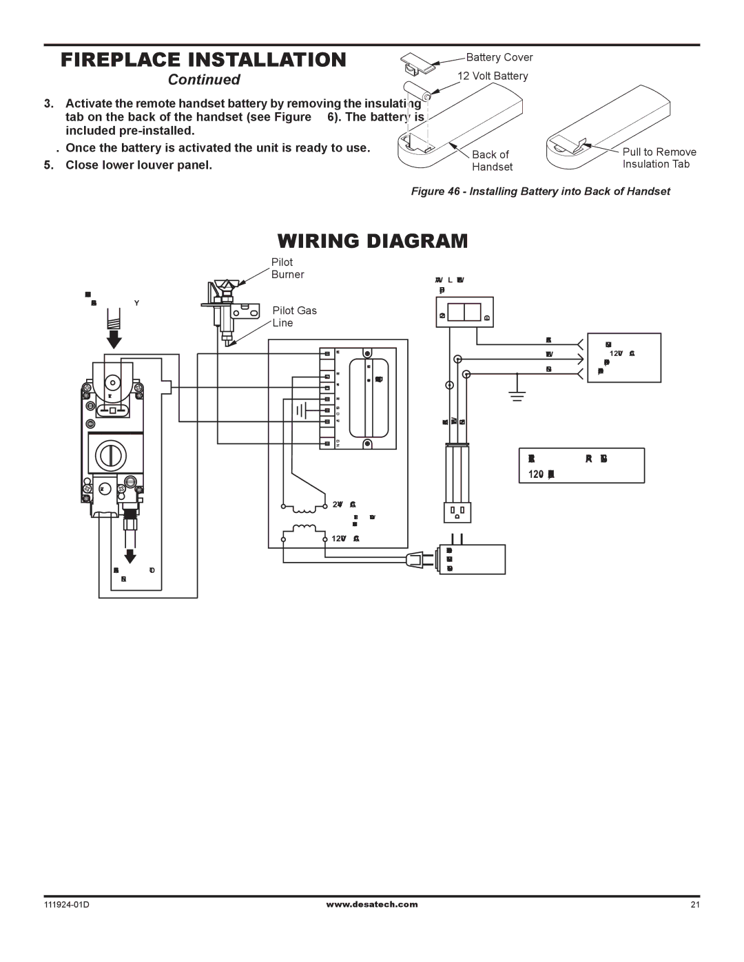
3.Activate the remote handset battery by removing the insulating tab on the back of the handset (see Figure 46). The battery is included
4.Once the battery is activated the unit is ready to use.
5.Close lower louver panel.
![]() Battery Cover
Battery Cover
12 Volt Battery
Back of | Pull to Remove |
Handset | Insulation Tab |
Figure 46 - Installing Battery into Back of Handset
INCOMING MAIN
GAS SUPPLY
EV1
EV2
GAS LINE TO
BURNER
Wiring Diagram
Pilot
![]() BurnerWALL SWITCH (SUPPLIED)
BurnerWALL SWITCH (SUPPLIED)
Pilot Gas |
|
| ON | OFF |
|
Line |
|
|
| ||
|
|
|
|
| |
|
|
|
| BLACK | INCOMING |
|
|
|
|
| |
MV |
|
|
| WHITE | 120V AC |
| MODEL SP745 IGNITION CONTROL |
|
| GREEN | (FUSE BOX |
TH PV/MV TR GND PV | Robertshaw |
| OR BREAKER) | ||
BLACK WHITE GREEN |
|
| |||
IGN |
|
|
|
|
|
ELECTRICAL RATING: 120v, 60Hz, 0.7A
24V AC
STEP DOWN
TRANSFORMER
120V AC
OPTIONAL
REMOTE
CONTROL
www.desatech.com | 21 |