10
VENTING INSTALLATION INSTRUCTIONS Installation Planning (Cont.)
VENTING INSTALLATION INSTRUCTIONS Continued
10.Place fireplace into position and shim with noncombustible material if needed. Nail or screw side flanges to framing to secure unit in place. IMPORTANT: Make sure fireplace is level before securing. If fireplace is not level it will not work properly.
Minimum Pipe | Siding Standoff | |
1 | /4" | |
Overlap 1 |
| |
|
| Screws |
Direct Vent |
|
|
Pipe |
|
|
Wall |
|
|
Firestop |
|
|
Maintain 1" |
|
|
|
|
|
Minimum Air |
|
|
|
|
|
Space Around |
|
|
|
|
|
Outer Pipe When |
|
|
|
| |
Penetrating a Wall |
|
| High Wind | ||
10 |
| /4" x | 10 | Termination | |
3 | Apply Mastic to | ||||
3 | /4" Framed | ||||
|
|
|
|
| |
Opening |
| Outside Edge of | |||
|
|
|
|
| Standoff |
|
|
|
|
| Exterior Wall |
|
|
|
|
| with Vinyl Siding |
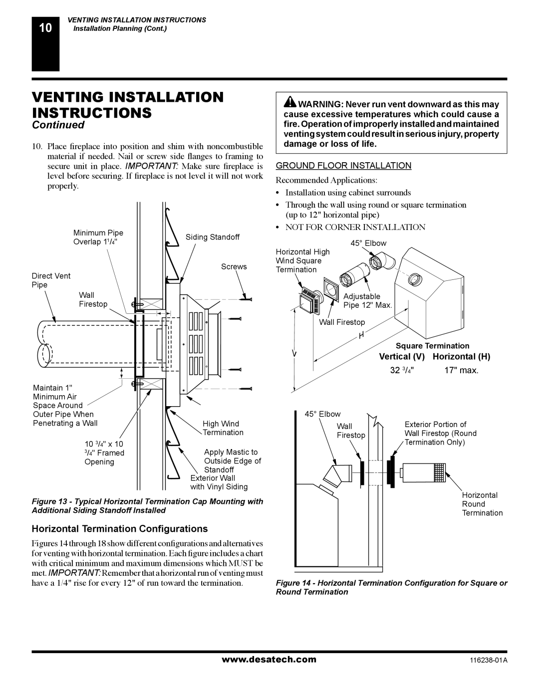
Figure 13 - Typical Horizontal Termination Cap Mounting with | |||||
Additional Siding Standoff Installed |
| ||||
Horizontal Termination Configurations
Figures 14 through 18 show different configurations and alternatives for venting with horizontal termination. Each figure includes a chart with critical minimum and maximum dimensions which MUST be met. IMPORTANT: Remember that a horizontal run of venting must have a 1/4" rise for every 12" of run toward the termination.
![]() WARNING: Never run vent downward as this may cause excessive temperatures which could cause a fire. Operation of improperly installed and maintained venting system could result in serious injury, property damage or loss of life.
WARNING: Never run vent downward as this may cause excessive temperatures which could cause a fire. Operation of improperly installed and maintained venting system could result in serious injury, property damage or loss of life.
GROUND FLOOR INSTALLATION
Recommended Applications:
•Installation using cabinet surrounds
•Through the wall using round or square termination (up to 12" horizontal pipe)
•NOT FOR CORNER INSTALLATION
45° Elbow
Horizontal High
Wind Square
Termination
Adjustable
Pipe 12" Max.
Wall Firestop
Square Termination
Vertical (V) Horizontal (H)
32 3/4" | 17" max. |
45° Elbow
Wall |
| Exterior Portion of | |||
Firestop |
| Wall Firestop (Round | |||
|
|
|
|
| Termination Only) |
|
|
|
|
|
|
|
|
|
|
|
|
|
|
|
|
|
|
|
|
|
|
|
|
Horizontal
Round
Termination
Figure 14 - Horizontal Termination Configuration for Square or Round Termination
www.desatech.com |