Manuals
/
Desa
/
Household Appliance
/
Indoor Fireplace
Desa
(V)V42ENA(1) Wiring Diagram, Wall Switch Installation, Fireplace Installation, Continued
Models:
(V)V42EPA(1)
(V)V42ENA(1)
1
24
38
38
Download
38 pages
8.84 Kb
21
22
23
24
25
26
27
28
Troubleshooting
Specification
Install
Parts list
Blower Wiring Diagram
Warranty
Observed Problem
DESA Venting Accessories
Pilot Assembly
Cleaning Glass Door
Page 24
Image 24
Page 23
Page 25
Page 24
Image 24
Page 23
Page 25
Contents
OWNER’S OPERATION AND INSTALLATION MANUAL
FOR YOUR SAFETY
FOR YOUR SAFETY WHAT TO DO IF YOU SMELL GAS
Do not touch any electrical switch
TABLE OF CONTENTS
SAFETY INFORMATION
WARNINGS
PRODUCT IDENTIFICATION
LOCAL CODES
Continued
SAFETY INFORMATION
PRODUCT FEATURES
PRE-INSTALLATION PREPARATION
LOCATION AND SPACE REQUIREMENTS
CLEARANCES
FRAMING AND FINISHING
PRE-INSTALLATION PREPARATION
Continued
LOCATION OF TERMINATION CAP
D E B L
V G V A
LOCATION OF TERMINATION CAP
VENTING INSTALLATION INSTRUCTIONS
INSTALLATION PRECAUTIONS
INSTALLATION PLANNING
Horizontal Termination Installation
VENTING INSTALLATION INSTRUCTIONS
Continued
VENTING INSTALLATION INSTRUCTIONS
VENTING INSTALLATION INSTRUCTIONS
Continued
Horizontal Termination Configurations
VENTING INSTALLATION INSTRUCTIONS
VENTING INSTALLATION INSTRUCTIONS
Continued
VENTING INSTALLATION INSTRUCTIONS
Continued
Recommended Applications
VENTING INSTALLATION INSTRUCTIONS
Continued
Venting with Two 90 Elbows
Venting with Two 90 Elbows
INSTALLATION FOR VERTICAL TERMINATION
Flat Ceiling Installation
VENTING INSTALLATION INSTRUCTIONS
Continued
Vertical Termination Configurations
VENTING INSTALLATION INSTRUCTIONS
Continued
Venting with Two 90 Elbows
HIGH ALTITUDE INSTALLATION
VENTING INSTALLATION INSTRUCTIONS
Continued
Vertical Venting
FIREPLACE INSTALLATION
INSTALLING OPTIONAL BLOWER ACCESSORY
DESA Venting Accessories
Model BK Installation
FIREPLACE INSTALLATION
8.Plug in blower power cord
Continued
Model BKT Installation
Blower Wiring Diagram
FIREPLACE INSTALLATION
Continued
INSTALLING GAS PIPING TO FIREPLACE LOCATION
FIREPLACE INSTALLATION
Continued
CONNECTING FIREPLACE TO GAS SUPPLY
Installation Items Needed
Pressure Testing Gas Supply Piping System
CHECKING GAS CONNECTIONS
Pressure Testing Fireplace Gas Connections
Cleaning Glass Door
See Cleaning and Maintenance on page
REMOVING/REPLACING GLASS DOOR
INSTALLING LOGS, LAVA ROCK AND GLOWING EMBERS
FIREPLACE INSTALLATION
Continued
FIREPLACE INSTALLATION
FIREPLACE INSTALLATION
Figure 41- Installing Log No
Figure 44 - Installing Log No
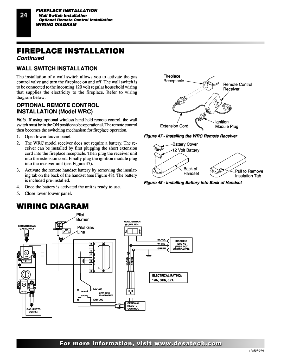
WIRING DIAGRAM
WALL SWITCH INSTALLATION
OPTIONAL REMOTE CONTROL INSTALLATION Model WRC
FIREPLACE INSTALLATION
FOR YOUR SAFETY READ BEFORE LIGHTING
OPERATING FIREPLACE
LIGHTING INSTRUCTIONS
TO TURN OFF GAS TO APPLIANCE
OPERATING OPTIONAL BLOWER ACCESSORY
PILOT ASSEMBLY
INSPECTING BURNERS
BURNER FLAME PATTERN
CLEANING AND MAINTENANCE
GLASS DOOR
PILOT AND BURNERS
LOGS
TROUBLESHOOTING
OBSERVED PROBLEM
POSSIBLE CAUSE
REMEDY
REMEDY
ing Gas Connections, pages 20 and
TROUBLESHOOTING
OBSERVED PROBLEM
ILLUSTRATED PARTS BREAKDOWN
MODELS
ILLUSTRATED PARTS BREAKDOWN
Models VV42ENA1, VV42ENSA1, VV42ENHA1
PARTS LIST
PARTS LIST
BURNER ASSEMBLY FOR MODELS VV42ENA1, VV42ENSA1
VV42ENHA1, VV42EPA1,3 VV42EPSA1, AND VV42EPHA1
ILLUSTRATED PARTS BREAKDOWN
PARTS LIST
PARTS LIST
PART
NUMBER
REPLACEMENT PARTS
SERVICE HINTS
TECHNICAL SERVICE
SPECIFICATIONS
OWNERS REGISTRATION FORM
TAPE
Postage Required
TAPE
ACCESSORIES
FLEXIBLE GAS LINE CONNECTOR - GA5081
REMOTE CONTROL KIT - WRC SERIES Not Shown
WALL MOUNTED ON/OFF SWITCH - GWMS2 Not Shown
LIMITED WARRANTY DIRECT-VENTFIREPLACE
NOT A UPC
WARRANTY INFORMATION
Top
Page
Image
Contents