4.To make the matching halves of the inside and outside corners, simply rotate the table to the
NOTE: A positive stop is provided to find this angle quickly. The saw blade is already tilted to the
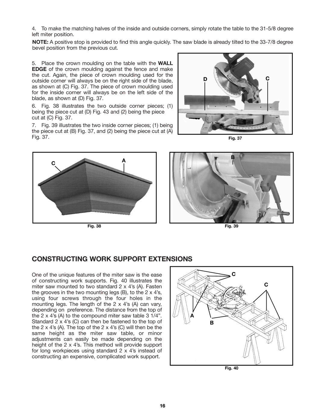
5.Place the crown moulding on the table with the WALL EDGE of the crown moulding against the fence and make the cut. Again, the piece of crown moulding used for the outside corner will always be on the right side of the blade, as shown at (C) Fig. 37. The piece of crown moulding used for the inside corner will always be on the left side of the blade, as shown at (D) Fig. 37.
6.Fig. 38 illustrates the two outside corner pieces; (1) being the piece cut at (D) Fig. 43 and (2) being the piece cut at (C) Fig. 37.
7.Fig. 39 illustrates the two inside corner pieces; (1) being the piece cut at (B) Fig. 37, and (2) being the piece cut at (A) Fig. 37.
DC
Fig. 37
C
A
B
Fig. 38 | Fig. 39 |
CONSTRUCTING WORK SUPPORT EXTENSIONS
One of the unique features of the miter saw is the ease of constructing work supports. Fig. 40 illustrates the miter saw mounted to two standard 2 x 4’s (A). Fasten the grooves in the two mounting legs (B), to the 2 x 4’s, using four screws through the four holes in the mounting legs. The length of the 2 x 4’s (A) can vary, depending on preference. The distance from the top of the 2 x 4’s (A) to the compound miter saw table 3 1/4”. Standard 2 x 4’s (C) can then be fastened to the top of the 2 x 4’s (A). The top of the 2 x 4’s (C) will then be the same height as the miter saw table, or minor adjustments can easily be made depending on the height of the 2 x 4’s. This method will provide support for long workpieces using standard 2 x 4’s instead of constructing an expensive, complicated work support.
![]() C
C
C
A![]()
B
Fig. 40
16
