STARTING PIN
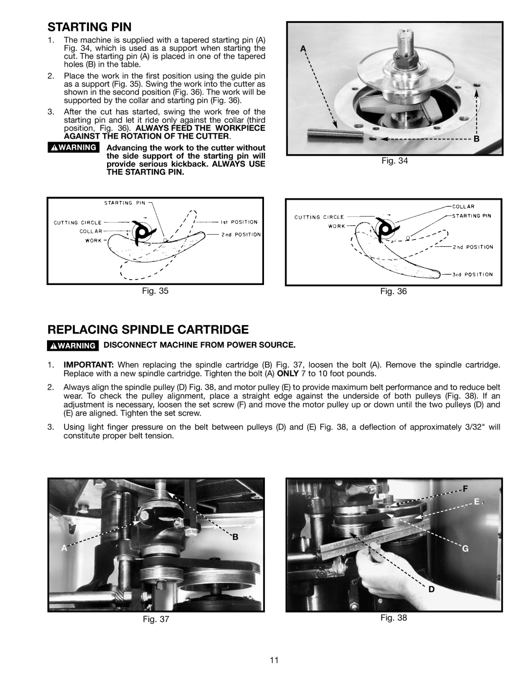
1.The machine is supplied with a tapered starting pin (A) Fig. 34, which is used as a support when starting the cut. The starting pin (A) is placed in one of the tapered holes (B) in the table.
2.Place the work in the first position using the guide pin as a support (Fig. 35). Swing the work into the cutter as shown in the second position (Fig. 36). The work will be supported by the collar and starting pin (Fig. 36).
3.After the cut has started, swing the work free of the starting pin and let it ride only against the collar (third position, Fig. 36). ALWAYS FEED THE WORKPIECE AGAINST THE ROTATION OF THE CUTTER.
Advancing the work to the cutter without the side support of the starting pin will provide serious kickback. ALWAYS USE THE STARTING PIN.
A
B
Fig. 34
Fig. 35 | Fig. 36 |
REPLACING SPINDLE CARTRIDGE
DISCONNECT MACHINE FROM POWER SOURCE.
1.IMPORTANT: When replacing the spindle cartridge (B) Fig. 37, loosen the bolt (A). Remove the spindle cartridge. Replace with a new spindle cartridge. Tighten the bolt (A) ONLY 7 to 10 foot pounds.
2.Always align the spindle pulley (D) Fig. 38, and motor pulley (E) to provide maximum belt performance and to reduce belt wear. To check the pulley alignment, place a straight edge against the underside of both pulleys (Fig. 38). If an adjustment is necessary, loosen the set screw (F) and move the motor pulley up or down until the two pulleys (D) and
(E) are aligned. Tighten the set screw.
3.Using light finger pressure on the belt between pulleys (D) and (E) Fig. 38, a deflection of approximately 3/32" will constitute proper belt tension.
B
A
Fig. 37
F
E
G
D
Fig. 38
11