ATTACHING TABLE INSERTS
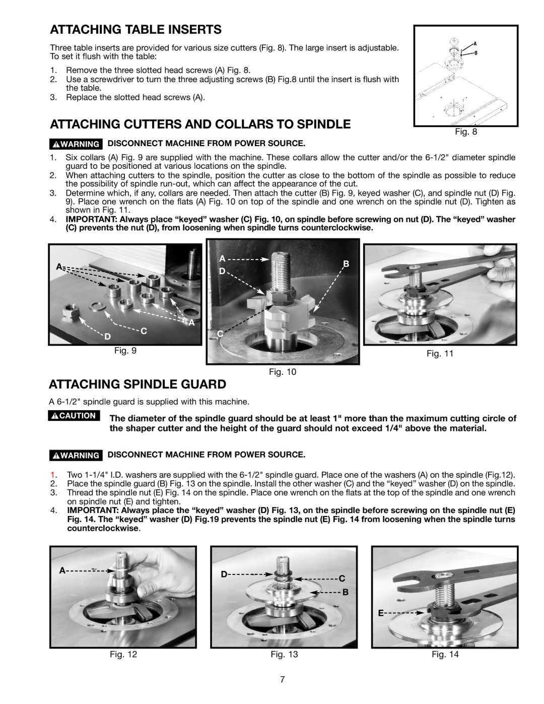
Three table inserts are provided for various size cutters (Fig. 8). The large insert is adjustable. To set it flush with the table:
1.Remove the three slotted head screws (A) Fig. 8.
2.Use a screwdriver to turn the three adjusting screws (B) Fig.8 until the insert is flush with the table.
3.Replace the slotted head screws (A).
ATTACHING CUTTERS AND COLLARS TO SPINDLE
DISCONNECT MACHINE FROM POWER SOURCE.
Fig. 8
1.Six collars (A) Fig. 9 are supplied with the machine. These collars allow the cutter and/or the
2.When attaching cutters to the spindle, position the cutter as close to the bottom of the spindle as possible to reduce the possibility of spindle
3.Determine which, if any, collars are needed. Then attach the cutter (B) Fig. 9, keyed washer (C), and spindle nut (D) Fig. 9). Place one wrench on the flats (A) Fig. 10 on top of the spindle and one wrench on the spindle nut (D). Tighten as shown in Fig. 11.
4.IMPORTANT: Always place “keyed” washer (C) Fig. 10, on spindle before screwing on nut (D). The “keyed” washer
(C) prevents the nut (D), from loosening when spindle turns counterclockwise.
A |
|
|
| A | B |
|
|
| D | ||
|
|
|
| ||
|
|
|
|
| |
|
|
| C | A |
|
| D |
| C |
| |
|
|
|
| ||
|
|
|
|
| |
|
| Fig. 9 |
|
| Fig. 11 |
|
|
|
|
|
Fig. 10
ATTACHING SPINDLE GUARD
A
The diameter of the spindle guard should be at least 1" more than the maximum cutting circle of the shaper cutter and the height of the guard should not exceed 1/4" above the material.
DISCONNECT MACHINE FROM POWER SOURCE.
1. Two
2.Place the spindle guard (B) Fig. 13 on the spindle. Install the other washer (C) and the “keyed” washer (D) on the spindle.
3.Thread the spindle nut (E) Fig. 14 on the spindle. Place one wrench on the flats at the top of the spindle and one wrench on spindle nut (E) and tighten.
4.IMPORTANT: Always place the “keyed” washer (D) Fig. 13, on the spindle before screwing on the spindle nut (E) Fig. 14. The “keyed” washer (D) Fig.19 prevents the spindle nut (E) Fig. 14 from loosening when the spindle turns counterclockwise.
A![]()
Fig. 12
D![]()
![]()
![]() C
C
![]()
![]() B
B
Fig. 13
E![]()
Fig. 14
7