not support this feature. Power Budgeting jumper P4 is designed to ensure proper configuration of the product.
The DISI board must be installed in a slot that can be allocated 25W.
If Power Budgeting is not implemented by a vendor's system, the DISI board must be plugged into a x4 or higher slot with the P4 jumper in position
If Power Budgeting is implemented by a vendor's system, the DISI board can be plugged into a x1 slot but the P4 jumper must be in position pins
WARNING! Installing the DISI board in a x1 slot with the P4 jumper in position
If the DISI will be connected to other telephony boards via a CT Bus cable, you should install the boards to minimize unused connectors on the CT Bus cable (in addition to ensuring that the power requirements are met):
■Install boards in adjacent slots whenever possible.
■If the DISI board will be connected to one or more PCI boards, use the PCI Express slot(s) closest to the PCI slots.
5. Installing the Board
WARNING! Unplug the equipment before performing the procedures described here. Failure to disconnect the power before you open the chassis can result in personal injury. Ensure that the system is disconnected from its power source and from all telecommunications links, networks, or modem lines whenever the chassis cover is removed. Do not operate the system with the cover removed.
CAUTION: To avoid possible damage to the board, remove power from the computer before beginning installation. Observe proper
To install the DISI board, perform the following steps:
1.Turn off all power to the system and disconnect the system’s power cords.
2.Remove the computer’s cover.
3.Choose an empty PCI Express expansion slot and remove the slot’s retaining screw and access cover plate.
4.Insert the board’s edge connector into the bus slot, and apply firm pressure to the top edge of the board until the board is fully seated in the edge connector.
5.Reinstall the retaining screw.
6.Repeat steps 1 through 5 for any additional boards you are installing.
7.Connect the telephony boards together with a CT Bus cable of the appropriate size (not included). If possible, use a cable assembly that matches the number of boards in your system. If the cable has more than one unused connector, install the cable so that all the unused connectors are at one end of the cable.
8.Replace the computer’s cover.
9.Reconnect the computer’s power cord.
Audio Cable and Ferrite Clamp
A ferrite clamp is required on the audio cable to reduce RFI emissions from the PCB audio jack and to comply with the EN55022 Class B radio frequency interference limits. Follow these instructions to properly install the ferrite clamp:
1.Loop the cable once around the ferrite clamp, keeping cable snug and as close as possible to the plug to be installed into audio jack on the PCB.
2.Snap the ferrite clamp closed onto the cable.
3.Insert the plug into the audio jack.
Connect to Power Supply
The DISI board must be connected to an external power supply. The power module is the MSISCGBLPWRMOD MSI Global Power Module Assembly. One power module is required per DISI baseboard.
The external power module generates
6. Telephony Connection Options
The station ports on the DISI board are accessed using a telephony connection box such as the breakout box provided with the DISIBOBKIT breakout box and cable kit. Alternatively, the CBLTAC0X32 Telco Adapter Cable can be used for installations with a
Connect Board Using DISIBOBKIT Breakout Box and Cable Kit
The breakout box can be mounted using screws or
■Mounting Breakout Box Using Screws
■Mounting Breakout Box Using
Connect Board Using CBLTAC0X32 Telco Adapter Cable
The CBLTAC0X32 Telco Adapter Cable converts the
The CBLTAC0X32 is approximately 12 inches in length. Standard 25 pair Amphenol* cables should be used to extend the reach.
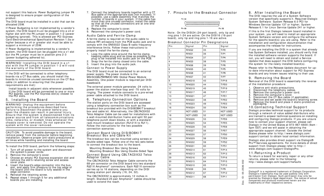
7. Pinouts for the Breakout Connector
Note: On the DISI24
Breakout Connector Pin Designations
Pin | Signal | Pin | Signal |
| |
|
|
|
|
| |
1 | RING2 | 35 | TIP2 |
| |
|
|
|
|
| |
2 | RING1 | 36 | TIP1 |
| |
|
|
|
|
| |
3 | RING4 | 37 | TIP4 |
| |
|
|
|
|
| |
4 | RING3 | 38 | TIP3 |
| |
|
|
|
|
| |
5 | RING6 | 39 | TIP6 |
| |
|
|
|
|
| |
6 | RING5 | 40 | TIP5 |
| |
|
|
|
|
| |
7 | RING8 | 41 | TIP8 |
| |
|
|
|
|
| |
8 | RING7 | 42 | TIP7 |
| |
|
|
|
|
| |
9 | RING18 | 43 | TIP18 |
| |
|
|
|
|
| |
10 | RING20 | 44 | TIP20 |
| |
|
|
|
|
| |
11 | RING19 | 45 | TIP19 |
| |
|
|
|
|
| |
12 | RING17 | 46 | TIP17 |
| |
|
|
|
|
| |
13 | RING21 | 47 | TIP21 |
| |
|
|
|
|
| |
14 | RING22 | 48 | TIP22 |
| |
|
|
|
|
| |
15 | RING23 | 49 | TIP23 |
| |
|
|
|
|
| |
16 | RING24 | 50 | TIP24 |
| |
|
|
|
|
| |
17 | NOT USED | 51 | NOT USED |
| |
|
|
|
|
| |
18 | NOT USED | 52 | NOT USED |
| |
|
|
|
|
| |
19 | RING26 | 53 | TIP26 |
| |
|
|
|
|
| |
20 | RING25 | 54 | TIP25 |
| |
|
|
|
|
| |
21 | RING28 | 55 | TIP28 |
| |
|
|
|
|
| |
22 | RING27 | 56 | TIP27 |
| |
|
|
|
|
| |
23 | RING30 | 57 | TIP30 |
| |
|
|
|
|
| |
24 | RING29 | 58 | TIP29 |
| |
|
|
|
|
| |
25 | RING32 | 59 | TIP32 |
| |
|
|
|
|
| |
26 | RING31 | 60 | TIP31 |
| |
|
|
|
|
| |
27 | RING14 | 61 | TIP14 |
| |
|
|
|
|
| |
28 | RING13 | 62 | TIP13 |
| |
|
|
|
|
| |
29 | RING16 | 63 | TIP16 |
| |
|
|
|
| 002- | |
30 | RING15 | 64 | TIP15 | ||
| |||||
|
|
|
|
| |
31 | RING10 | 65 | TIP10 | 2536 | |
|
|
|
| ||
32 | RING9 | 66 | TIP9 | ||
|
|
|
| 05- | |
33 | RING12 | 67 | TIP12 | ||
|
|
|
| ID:Doc. | |
34 | RING11 | 68 | TIP11 | ||
| |||||
|
|
|
|
|
8. After Installing the Board
The DISI requires the use of a System Software version that specifically supports it. Required Dialogic System Software: System Release 6.0 PCI for Windows Service Update 137 or higher; System Release 6.1 for Linux Service Update 241 or higher.
If this is the first Dialogic telecom board installed in your system, you will need to install an appropriate System Software version and configure the software for the specific board(s) you are using. Refer to the installation and configuration documentation that accompanies the release for instructions.
If you are installing the DISI in a system that already has System Software installed, you should verify that the installed software version supports the board. If not, you will need to obtain and install a Service Update that does support the DISI before configuring the system for the newly installed board(s).
Please refer to the Release Update document for up-
9. Removing the Board
Removal of the DISI board is essentially the reverse of the installation procedure:
1.Observe
2.Disconnect the telephony cables.
3.Remove the computer’s power cord.
4.Remove the computer’s cover.
5.Disconnect the CT Bus cable (if applicable).
6.Remove and set aside the board’s retaining screw.
7.Remove the board and place it
10.Contacting Technical Support
Dialogic provides technical support for its products through a network of value added distributors who are trained to answer technical questions on installing and configuring Dialogic products. If you are unsure how to contact your support channel, please call Dialogic in the United States at
Dialogic also provides direct support via Dialogic® Pro™ Services agreements. For more details of direct support from Dialogic please refer to http:// www.dialogic.com/support/DialogicPro.
11.Returning a Product
To return a board for warranty repair or any other returns, please refer to the following: http://www.dialogic.com/support/hwfaults
Dialogic® is a registered trademark of Dialogic Corporation. Dialogic's trademarks may be used publicly only with permission from Dialogic. Such permission may only be granted by Dialogic’s legal department. The names of actual companies and products mentioned herein are the trademarks of their respective owners.